Gas Turbine Topping in Sulfuric Acid Manufacture

a gas turbine and sulfuric acid technology, applied in the direction of sulfur compounds, inorganic chemistry, jet propulsion plants, etc., can solve the problems of not being able to burn all the sulfur required, damage to the turbine blades, and not being able to achieve the effect of maximum energy recovery

Inactive Publication Date: 2009-09-24
WOJAK BOGDAN
View PDF11 Cites 8 Cited by
  • Summary
  • Abstract
  • Description
  • Claims
  • Application Information

AI Technical Summary

Benefits of technology

[0017]The sulfur dioxide discharged from the gas turbine is then used downstream to generate steam for driving a steam turbine (that is separate and distinct from the gas turbine) to generate additional electrical power. The gas turbine thus acts as a “topping device” preceding the steam-raising system. In other words, the waste heat created when sulfuric acid is manufactured can be harnessed using two separate and distinct electricity-generating turbines, namely the (downstream) steam turbine and the (upstream) gas turbine. The latter, by virtue of the present invention, can be driven with partially cooled sulfur dioxide from the combustion reaction occurring in the sulfur-burning combustor. By mixing a cooler gas (air or recycled sulfur dioxide) with the hot sulfur dioxide gas emerging from the combustor, the resulting mixture is cooled to a manageable temperature that does not cause heat damage to the turbine blades of the gas turbine (of the so-called topping device), thus enabling maximal energy recovery from the production of sulfuric acid.

Problems solved by technology

However, as Applicant has realized, such an implementation would, in reality, be precluded by the maximum temperature constraints of the turbine.
Accordingly, as Applicant has realized, it is not technically feasible to combust sulfur and to directly discharge the extremely hot sulfur dioxide directly into a gas turbine for energy extraction as this would cause heat-induced damage to the turbine blades.
For example, in the Tyne gas turbine, the air temperature at the exit of the compressor is approximately 650 K (for a compression ratio of 13.5) and the maximum turbine entry temperature is approximately 1150 K. Thus, it is clearly not possible to burn all the sulfur required.
This obviates the possible need for a separate refractory-lined burner, fed by the engine compressor and exhausting to the turbine, which would be a potentially very hazardous pressure vessel and would add serious complication and expense to the gas turbine engine installation.

Method used


Image

  • Gas Turbine Topping in Sulfuric Acid Manufacture
  • Gas Turbine Topping in Sulfuric Acid Manufacture
  • Gas Turbine Topping in Sulfuric Acid Manufacture

Examples


example 1

[0045]A gas mixture containing 65.5 percent by volume (64,328 kg / hr) of sulfur dioxide, 34.0 percent by volume (16,309 kg / hr) of oxygen, and 0.5 percent by volume (213 kg / hr) of inert gas was delivered under a pressure of 15 atm and at temperature of 650° C. into the ejector, where the gas mixture was mixed with a circulating gas.

[0046]At the exit from the injector, the gas composition was follows: 0.04 percent by volume 78 kg / hr) of sulfur trioxide, 49.2 percent by volume (71,269 kg / hr) of sulfur dioxide, 37.94 percent by volume (268,249 kg / hr) of oxygen, and 12.82 percent by volume (79,327 kg / hr) of nitrogen. The temperature of the gas mixture was 350 to 550° C. and the pressure was 10 atmospheres.

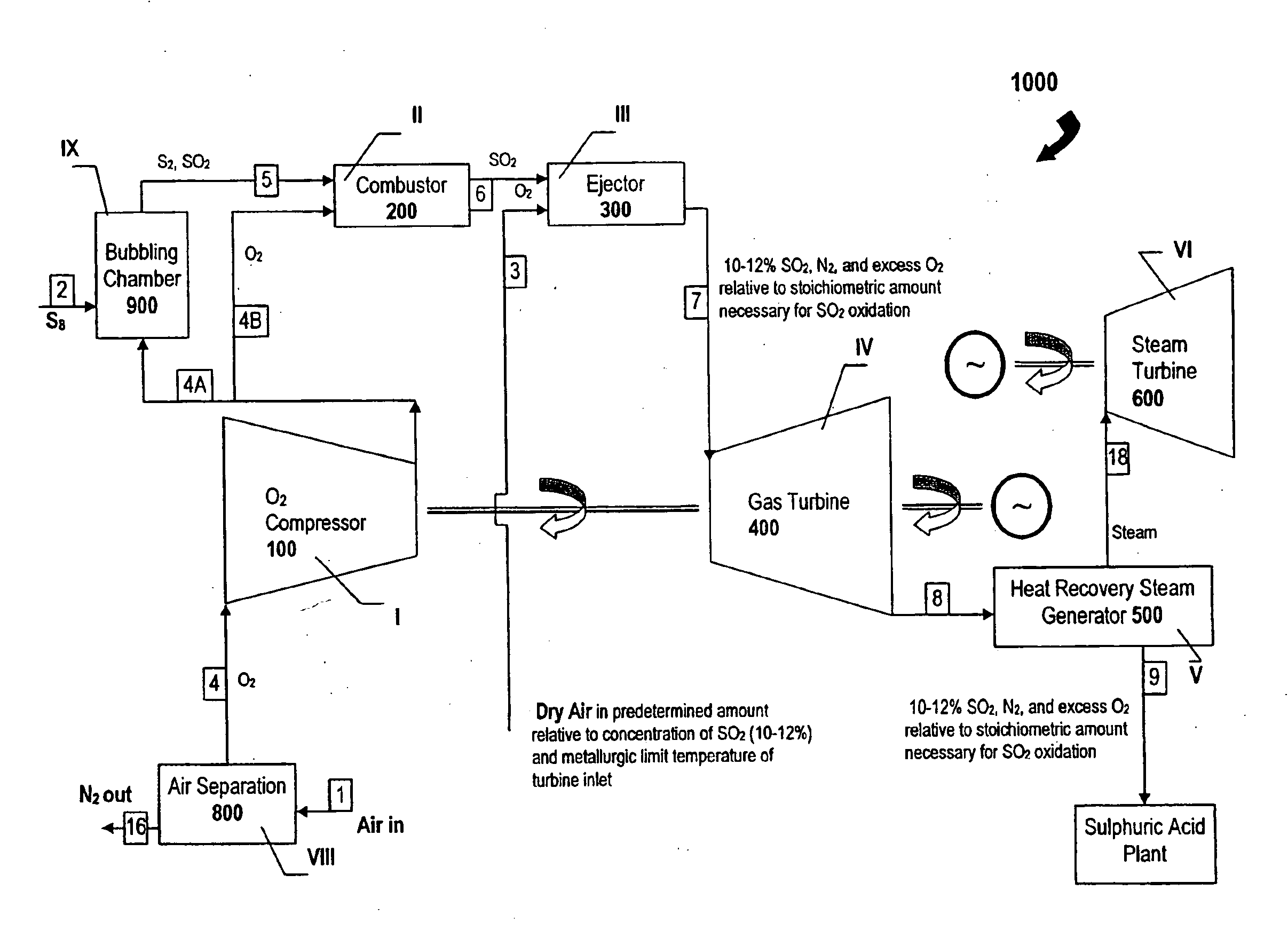
[0047]As is shown in FIG. 6 and FIG. 8, the sulfur dioxide and the sulfur vapor exits from the vaporizer (bubbling chamber) 900 at stage IX as stream 5 at a temperature not exceeding 700-800° C. and is then directed into the combustor 200 at stage III. Secondary oxygen in a stoichiometri...

example 2

[0055]In this particular example, the cross-sectional area of the bubbling chamber (FIG. 5) was about 3 m2, and its diameter was 2 meters. The height of the sulfur melt was maintained at 1 metre (under stationary conditions). The bubbling chamber was an apparatus 3.5 m high. The height of the separation space above the melt was 0.8 m, and the height of the settling zone was 1.2 m. The hot, low-viscosity sulfur at a temperature of 140-150° C. was delivered into a bubbling chamber. The consumption rate of sulfur was 7370 kg / hr. Technical oxygen, containing up to 2% by volume of inert gas, was used.

[0056]The process was effected under a pressure of 10 atm and at a temperature of the melt equal to the boiling point of sulfur at a given pressure −646.1° C. (according to The Sulfur Data Book, Freeport Sulfur Company (1954)). This temperature was maintained in the bubbling chamber by the heat liberated in the oxidation reaction of part of the sulfur with oxygen as it was bubbled through th...

example 4

[0059]In this further example, the process was carried out as described in Example 1, except that the pressure was 25 atm, and the temperature of the molten sulfur was maintained at 650° C., which was below the boiling point of sulfur at this pressure. Excess heat was withdrawn by heat-exchangers that were located directly in the molten sulfur bed. Liquid sulfur having a temperature of 140-150° C. was a delivered into bubbling chamber at a rate of −30,234 kg / hr. The height of the molten sulfur bed was 3 metres, and its height was 16 metres. Technical oxygen was delivered into the apparatus under a pressure of 25 atm at a rate of −4559.9 kg / hr. The amount of delivered nitrogen was −20 kg / hr.

[0060]The gaseous mixture discharged from the bubbling chamber consisted of sulfur vapor −25,675 kg / hr, which was 81.2% per volume, sulfur dioxide −9120 kg / hr, which was 18.4% per volume, and inert gases −20 kg / hr or 0.42% per volume.


PUM


Abstract

A method of generating electrical power using sulfur, the method having the steps of combusting oxygen with a stoichiometric quantity of sulfur comprising predominantly diatomic sulfur to generate hot sulfur dioxide gas; and mixing a cooling gas substantially cooler than the hot sulfur dioxide gas with the hot sulfur dioxide gas to produce a mixed working gas for driving a gas turbine, the mixed working gas having a temperature less than a maximum allowable temperature determined by a metallurgic limit of turbine blades in the gas turbine, whereby the gas turbine generates electrical power.

Description

TECHNICAL FIELD[0001]The invention relates generally to a method of generating electrical power using sulfur and, in particular, to combustion of sulfur in a gas turbine generator.BACKGROUND[0002]Apart from certain limitations imposed by the chemistry of the conversion stage, the steam-raising system associated with a sulfuric acid plant is fairly conventional (FIG. 1). Furthermore, in a typical sulfuric acid plant, so long as the air supply to the sulfur burner is rigorously dried, ordinary steels may be used throughout the plant with no serious corrosion problems. Subsequently, with the increasing use of gas turbines in conventional electricity plants, both as the prime driver and as “topping” devices preceding a steam-raising system, the same techniques were proposed for the energy recovery from sulfuric acid manufacture. For a typical case, the net energy recovery as electric power can be improved by 60-70 percent over that possible with simple steam-raising equipment (see R. T....

Claims


Application Information

Patent Timeline
Patent Type & Authority Applications(United States)
IPC IPC(8): F02C3/20F02C3/30F02C3/34F02C6/04
CPCC01B17/54F02C3/32F02C3/30C01B17/76Y02P20/129
Inventor WOJAK, BOGDAN
Owner WOJAK BOGDAN
Why Eureka
Try Eureka