Control apparatus for controlling power conversion apparatus
a technology of power conversion apparatus and control apparatus, which is applied in the direction of process and machine control, pulse technique, instruments, etc., can solve the problems of large variation in the neutral-point voltage of the motor, and the noise of switching elements having such a high switching speed tend to exceed the threshold, so as to achieve high reliability and accuracy.
- Summary
- Abstract
- Description
- Claims
- Application Information
AI Technical Summary
Benefits of technology
Problems solved by technology
Method used
Image

Examples
first embodiment
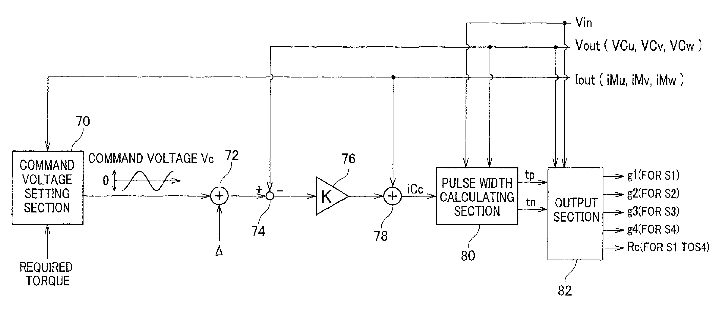
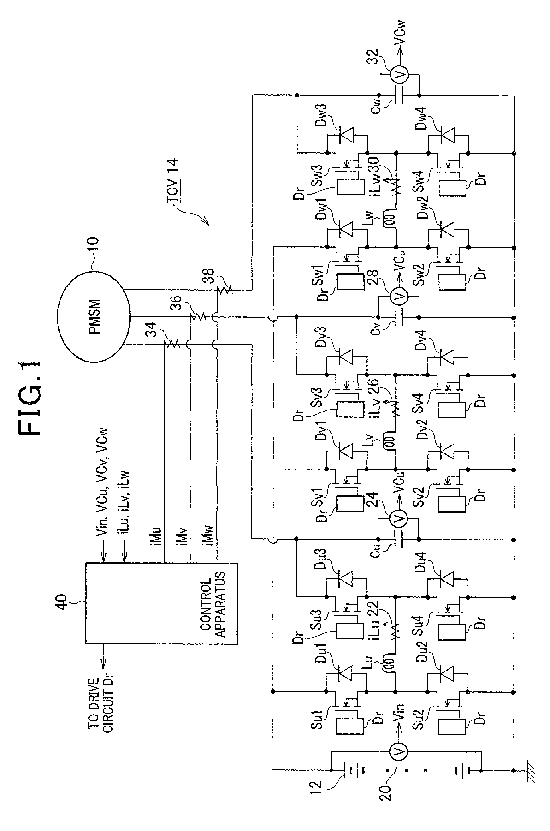
[0033]FIG. 1 is a diagram showing an overall structure of a control system including a power conversion apparatus and a control apparatus for controlling the output voltage of the power conversion apparatus according to a first embodiment of the invention.
[0034]In this figure, the reference character 10 denotes a permanent magnet type synchronous motor (PMSM) used as a drive power generating apparatus of a hybrid vehicle, 12 denotes a high voltage battery which may be a nickel hydrogen storage battery or a lithium ion storage battery, 14 denotes a three-phase converter (TCV) as the power conversion apparatus which supplies electric power to the motor 10, and 40 denotes the control apparatus. The motor 10 is connected to the high voltage battery 12 through the TCV 14.
[0035]The TCV 14 includes three converters provided for the respective three phases of the motor 10, each of which is capable of varying its output voltage continuously. In this embodiment, the converters constituting th...
second embodiment
[0089]Next, a second embodiment of the invention is described below with focus on the difference with the first embodiment.
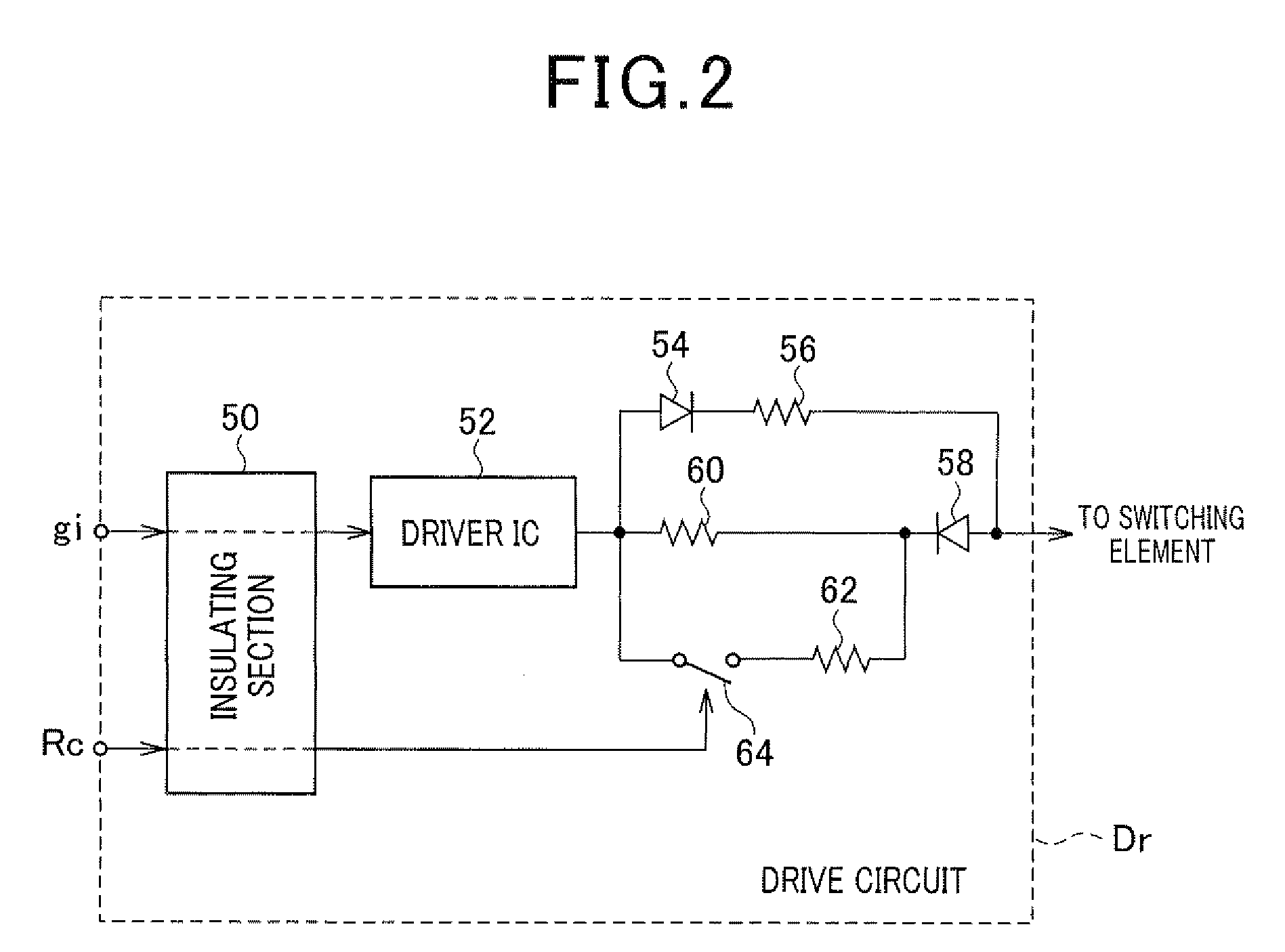
[0090]FIG. 14 is a diagram showing a circuit structure of the drive circuit Dr used in the second embodiment. In FIG. 14, the same reference characters as those shown in FIG. 2 denote the same or equivalent components.
[0091]As shown in FIG. 14, in this embodiment, the drive circuit Dr includes a plurality of resistors 62a having different resistances, and a selector for connecting required one or ones of the resistors 62a between the gate of the switching element Si and the driver IC 52. This makes it possible to adjust the resistance of the electric path for discharging the charge in the gate of the power switching element Si in multistage.
[0092]Next, a manner of setting the gate resistance Rg in this embodiment is explained with reference to FIGS. 15A and 15B.
[0093]FIG. 15A shows a relationship between the drain current and the gate resistance Rg, and FIG. 15B...
third embodiment
[0094]Next, a third embodiment of the invention is described below with focus on the difference with the first embodiment.
[0095]In this embodiment, the on-time period is measured in the drive circuit Dr on the basis of the operation command signal gi instead of outputting the resistance value command signal Rc from the control apparatus 40, the coil current is estimated on this measured on-time period, and the gate resistance Rg is adjusted in accordance with this estimated coil current.
[0096]FIG. 16 is a flowchart showing a process for adjusting the gate resistance Rg performed at regular time intervals by the drive circuit Dr.
[0097]This process begins by determining at step S20 whether or not the operation command signal gi has come up.
[0098]Step S 20 is provided to determine whether it is timing to switch the power switching element Si from off-state to on-state. If the determination result at step S20 is affirmative, the process proceeds to step S22 where a counter to measure th...
PUM
 Abstract
Description
Claims
Application Information
 - R&D
- Intellectual Property
- Life Sciences
- Materials
- Tech Scout
- Unparalleled Data Quality
- Higher Quality Content
- 60% Fewer Hallucinations
Browse by: Latest US Patents, China's latest patents, Technical Efficacy Thesaurus, Application Domain, Technology Topic, Popular Technical Reports.
© 2025 PatSnap. All rights reserved.Legal|Privacy policy|Modern Slavery Act Transparency Statement|Sitemap|About US| Contact US: help@patsnap.com