
Particulate Matter Pruifying Device and Manufacturing Method thereof

a pruifying device and particle technology, applied in physical/chemical process catalysts, metal/metal-oxide/metal-hydroxide catalysts, separation processes, etc., can solve the problem of catalyst may not always be carried densely on the surface of the filter substrate, and the activation region is limited within the range of several nm, so as to prevent excessive accumulation of particulate matter

Inactive Publication Date: 2009-10-01
TOYOTA JIDOSHA KK
View PDF16 Cites 3 Cited by
  • Summary
  • Abstract
  • Description
  • Claims
  • Application Information

AI Technical Summary

Benefits of technology

[0010]The present invention has been conceived noting the aforementioned technical problems, and has an object to provide a particulate matter purifying device capable of preventing particulate matter from being deposited excessively on an outer surface of a filter substrate, and to provide a manufacturing method thereof.
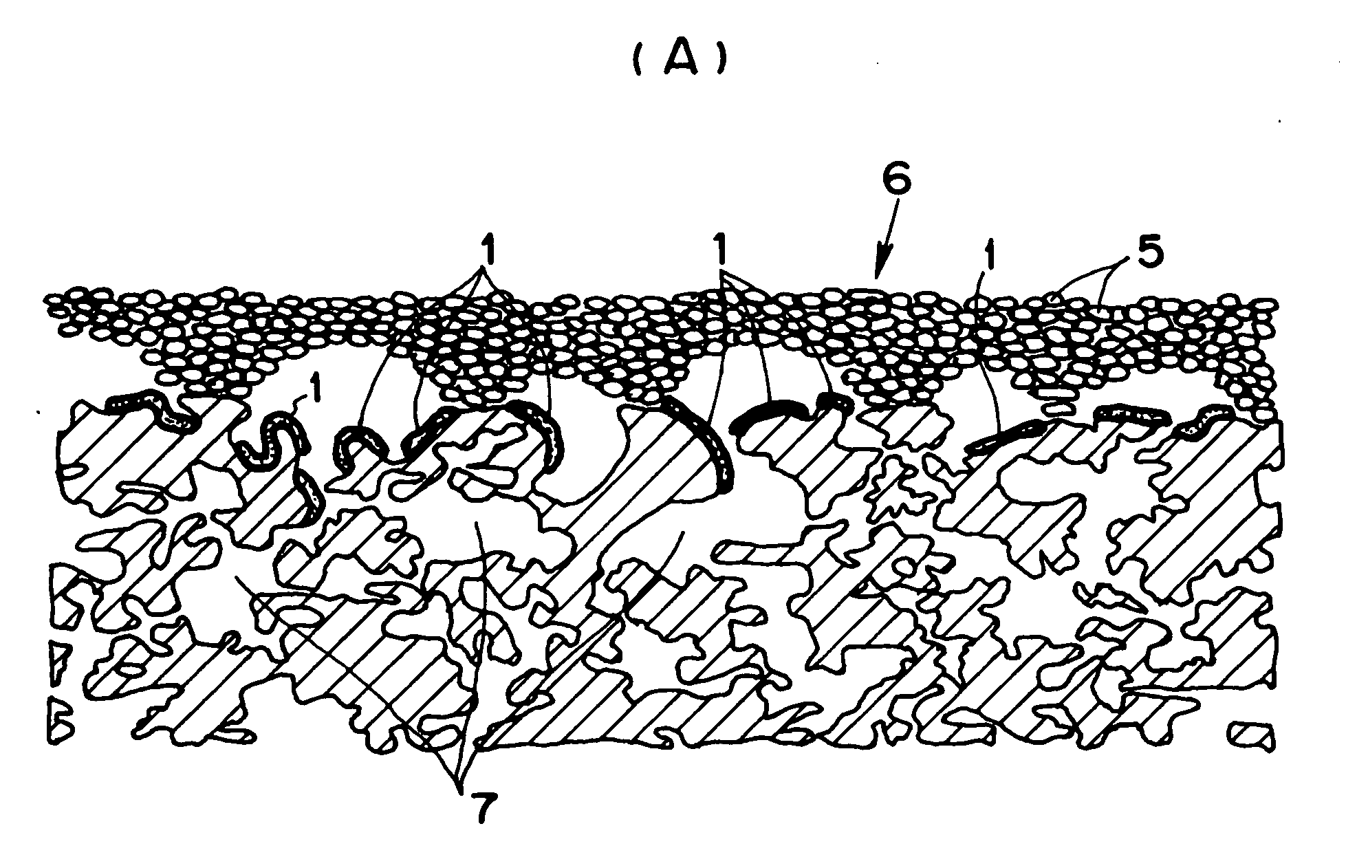
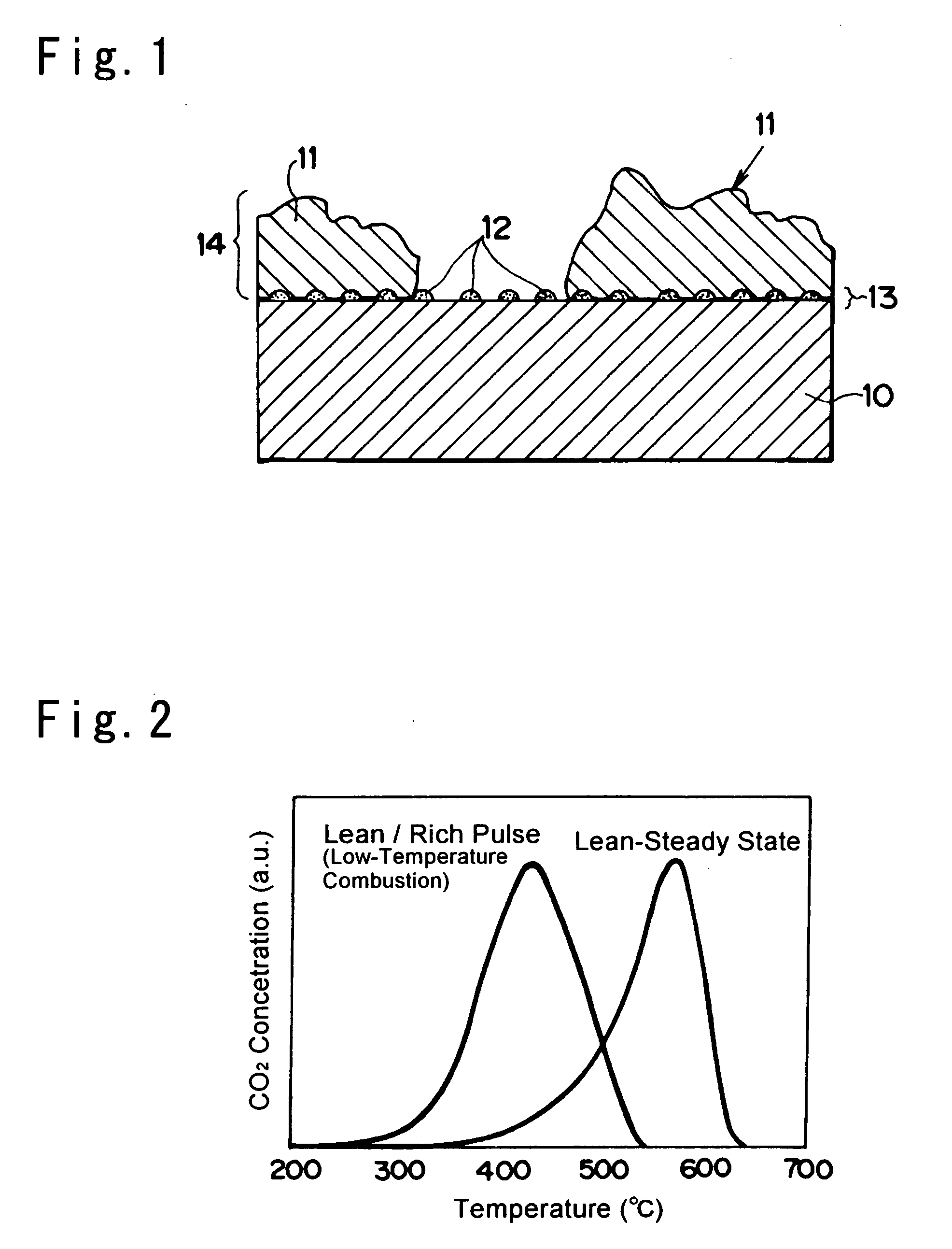
[0019]According to the invention, the active oxygen producing fine particles are thus carried on the surface of the filter substrate between the catalyst elements. Therefore, the particulate matter adhering between the catalyst elements is oxidized by the active oxygen produced by the active oxygen producing fine particles. As a result, the particulate matter is oxidized and removed. Specifically, the particulate matter is damaged by the active oxygen so that the oxidization of the particulate matter is facilitated, and the particulate matter is thereby removed. For this reason, an excessive deposition of the particulate matter resulting from adhesion and growth thereof can be avoided or minimized even if the filter substrate has a portion where there is no catalyst element.
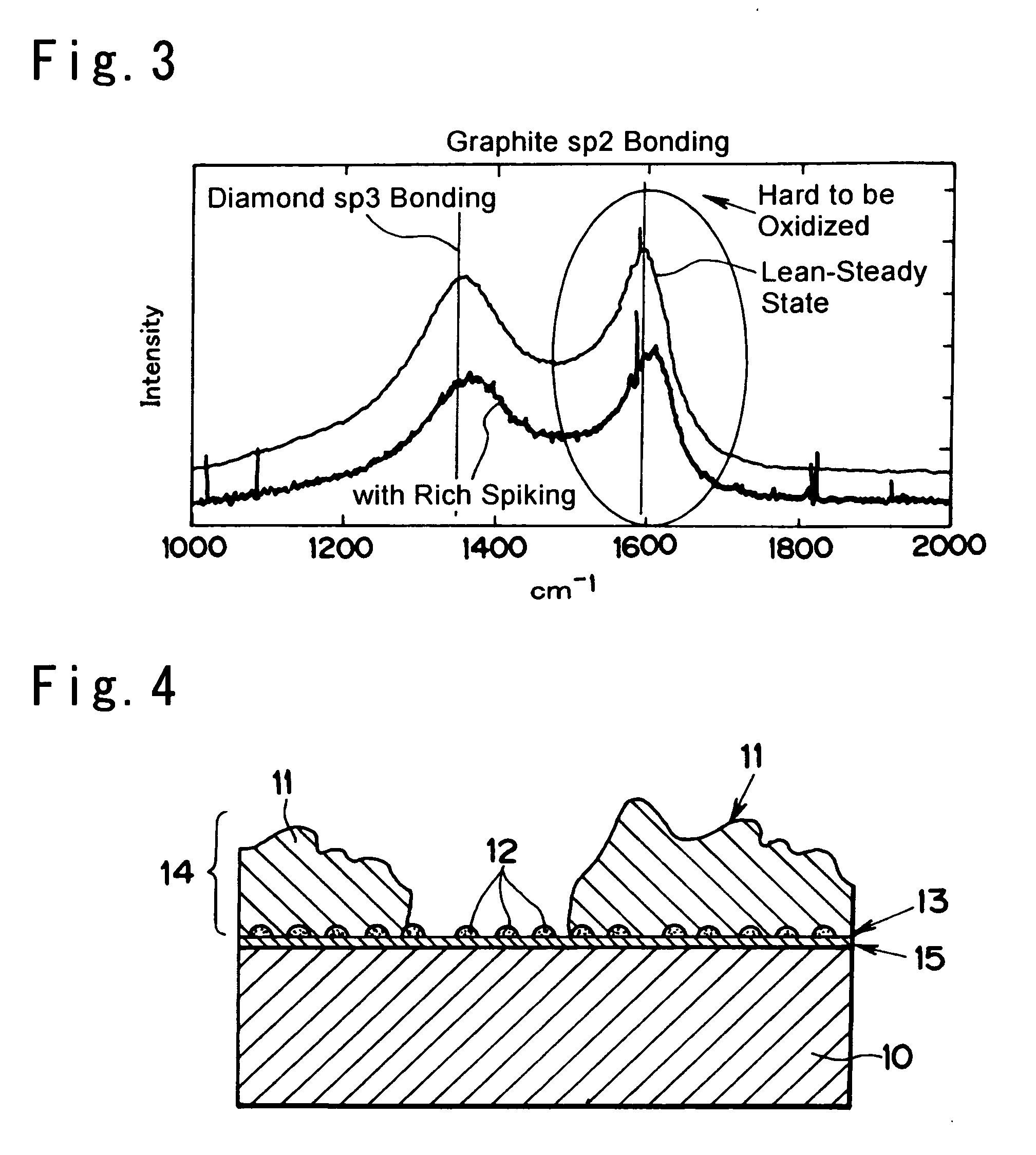
[0020]Also, according to the invention, even if the catalyst elements are isolated from each other so that the uncoated area exists therebetween, the active oxygen producing fine particulate layer is formed underneath the catalyst carrying layer, and partially exposed on the uncoated area. Therefore, the surface of the filter substrate can be prevented from being directly exposed as the uncoated area, or the uncoated area can be minimized. Thus, the above-explained structure of the invention can be achieved. For this reason, even if the filter substrate has a portion where the catalyst element does not exist on its surface, an excessive deposition of the particulate matter resulting from adhesion and growth thereof can be avoided or minimized.
[0022]Further, according to the invention, the solution of lipophilic group is adsorbed to the filter substrate as a preparation for the operation to carry the active oxygen producing fine particles. Namely, the solution has excellent affinity for the filter substrate, and it charges the surface of the filter substrate to the plus polarity. When a solution containing ions or complex ions of metallic element of the active oxygen producing fine particles (i.e., oxide particles or compound oxide particles) is contacted with the surface of the filter substrate charged to plus polarity, said ions or complex ions adhere to the filter substrate. As a result, the active oxygen producing fine particles can be adsorbed homogeneously so that the active oxygen producing fine particulate layer can be formed homogeneously. For this reason, it is possible to prevent from leaving the uncoated area where the surface of the filter substrate is exposed directly between the catalyst elements.

Problems solved by technology

However, the activation region is limited within the range of several nm from the place where the active oxygen is produced.
However, since the catalyst is a particulate material, the catalyst may not always be carried densely on the surface of the filter substrate.
As a result, an amount of the trapped particulate matter 5 may be accumulated excessive.

Method used


Image

  • Particulate Matter Pruifying Device and Manufacturing Method thereof
  • Particulate Matter Pruifying Device and Manufacturing Method thereof
  • Particulate Matter Pruifying Device and Manufacturing Method thereof

Examples


example 1

[0047]First of all, 2 liters of cordierite for the filter substrate was dipped into an aqueous solution prepared by dissolving 70 gram of metallic alkoxide such as aluminum alkoxide (aluminum tri-sec-butoxide, to be abbreviated as “ASBD” hereinafter) into 4 liters of a nonpolar solvent of cyclohexane. After lifting the cordierite substrate from the solution, extra solution was blown off, and then the cordierite substrate was dried and sintered. As a result, alumina was produced on the cordierite substrate homogeneously.

[0048]Then, particle CeZrO4 as the active oxygen producing fine particles was adsorbed to the cordierite substrate where alumina was separated out, by the complex ion adsorption method. Specifically, in order to prepare a complex ionic solution as a mixed liquid of zirconium and cerium, 0.05 mols of oxynitrate zirconium and cerium nitrate were collected individually, and dissolved in 4 liters of distilled water. Then, 118 g of ammonium dihydrogen citrate, and 61 g of ...

example 2

[0060]First of all, 136 g of benzalkonium chloride was dissolved in 4 liters of distilled water. Then, a filter substrate of cordierite was dipped in the prepared aqueous solution and left for about 30 minutes.

[0061]Apart from above, in order to prepare a complex ionic solution as a mixed liquid of zirconium and cerium, 0.05 mols of oxynitrate zirconium and cerium nitrate were collected individually, and dissolved in 4 liters of distilled water. Then, 118 g of ammonium dihydrogen citrate, and 61 g of ammonium citrate tribasic were added into the solution.

[0062]After lifting the filter substrate from the solution of benzalkonium chloride, extra solution was blown off. Then, the filter substrate was dipped in the solution of oxynitrate zirconium and cerium nitrate to adsorb the complex ions. In order to promote the diffusion of the solution, the filter substrate was moved up and down in the solution, and this absorption process was continued for one hour. As a result, zirconium comple...


PUM

PropertyMeasurementUnit
distanceaaaaaaaaaa
diameteraaaaaaaaaa
temperatureaaaaaaaaaa

Abstract

To provide a particulate matter purifying device which is capable of providing excessive deposition of particulate matter.In the particulate matter purifying device, a catalyst element 11 is carried on a porous filter substrate 10 through which an exhaust gas passes. The particulate matter purifying device traps particulate matter contained in the exhaust gas, and oxidizing the trapped particulate matter to remove. This particulate matter purifying device is characterized in that active oxygen producing fine particles 12 are carried on a surface of the filter substrate 10 between the catalyst elements 11. Therefore, the particulate matter is partially damaged by the active oxygen produced by the active oxygen producing fine particles 12. Consequently, oxidization of the particulate matter is promoted so that deposition of the particulate matter is prevented or minimized.

Description

TECHNICAL FIELD[0001]This invention relates to a device comprising a catalyst for purifying combustion exhaust gas of a diesel engine or the like, and more particularly, to a catalyst for removing particulate matter, especially carbon soot particles contained in the exhaust gas, and to a manufacturing method thereof.BACKGROUND ART[0002]A filter for removing particulate matter from an exhaust gas emitted to the atmosphere is known in the art. For example, Japanese Patent Laid-Open No. 9-94434 discloses a wall flow type waste gas purifying filter. According to the invention disclosed in Japanese Patent Laid-Open No. 9-94434, the particulate matter is trapped in the pores formed in a filter substrate when the exhaust gas passes therethrough, and the particulate matter is oxidized by a catalyst carried inside of the pores.[0003]Japanese Patent Publication No. 07-106290 discloses a catalyst mixture consisting essentially of a platinum group metal and an alkaline earth metal oxide which i...

Claims


Application Information

Patent Timeline
Patent Type & Authority Applications(United States)
IPC IPC(8): F01N3/20B21D51/16
CPCB01D53/944B01D2255/908B01J23/58B01J23/63Y10T29/49345F01N3/0222F01N3/033F01N2250/02Y02T10/20B01J37/0244Y02T10/12
Inventor TAKESHIMA, SHINICHIHAYASHI, KOTAROYOSHIDA, KOHEIHAYASHI, ATSUSHI
Owner TOYOTA JIDOSHA KK
Learn More