Chiller unit, refrigeration system having chiller unit and air conditioner having chiller unit

a chiller unit and chiller technology, which is applied in the direction of static/dynamic balance measurement, instruments, and domestic cooling apparatus, can solve the problems of excessive cooling and freezing of water medium, damage to water medium pipes or pumps for making water medium flow, and high labor requirements for so as to reduce labor and reduce the work associated with installation of chiller units, the effect of substantially accurately detecting

Inactive Publication Date: 2009-10-01
PANASONIC INTELLECTUAL PROPERTY MANAGEMENT CO LTD
View PDF12 Cites 26 Cited by
  • Summary
  • Abstract
  • Description
  • Claims
  • Application Information

AI Technical Summary

Benefits of technology

[0032]According to the present invention, the paddle type flow switch is provided in the chiller unit, and thus the labor imposed on the work associated with the installation of the chiller unit can be reduced. Furthermore, the flow switch is provided at the lower stage portion in which the space can be secured, and thus the maintenance performance of the flow switch can be enhanced the flow switch is provided at the place in the water medium pipe where the effect of the vibration is little, so that the malfunction caused by the vibration can be prevented, and thus the flow of water medium can be substantially accurately detected.
[0033]Furthermore, according to the present invention, by using the third function provided to the controller of t...

Problems solved by technology

In the chiller unit, water medium is excessively cooled and frozen in a heat exchanger.
When the chiller unit is actuated under the state that the water medium is frozen, a water medium pipe or a pump for making water medium flow may be damaged.
In this type of chiller unit, it is required to perform a work of externally quipping a flow switch for detecting freeze to a predetermined position of a water medium pipe connected to the chiller unit after the chiller unit is installed outdoors, and also it is required to perform various adjustments of the flow switch, so that much labor is required to the works associated with the installation of the chiller unit.
Furthermore, when the flow switch is provided in the chiller unit, maintenance of the flow switch is difficult because the plural divisional plate type heat exchangers and the pipe group for splitting refrigerant and water medium are laid down at the bottom portion of the chiller unit main body.
The flow switch easily carries out false detection due to vibration.
Therefore, when the flow switch is provided in the chiller unit, it is easily affected by vibration of a compressor or the like constituting a refrigeration cycle which is disposed adjacent...

Method used


Image

  • Chiller unit, refrigeration system having chiller unit and air conditioner having chiller unit
  • Chiller unit, refrigeration system having chiller unit and air conditioner having chiller unit
  • Chiller unit, refrigeration system having chiller unit and air conditioner having chiller unit

Examples


first embodiment

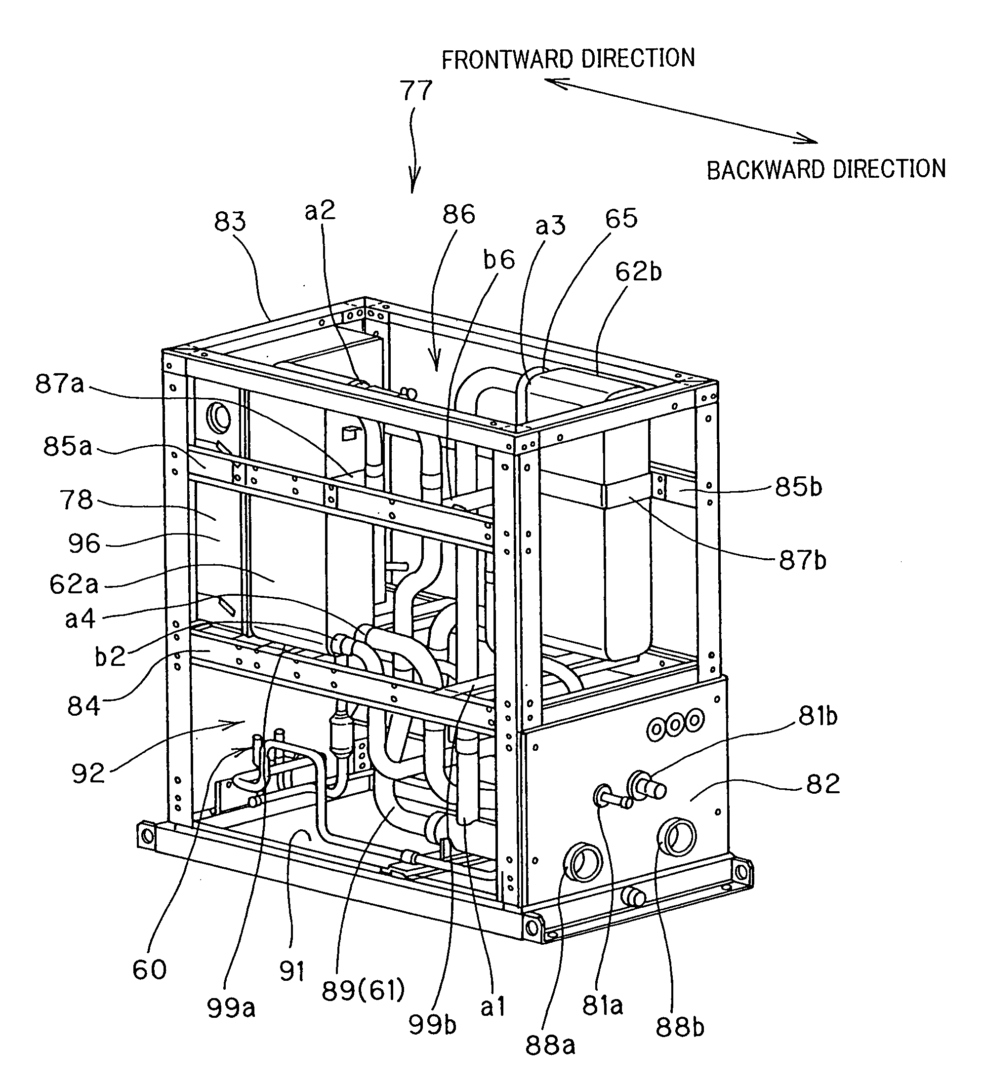
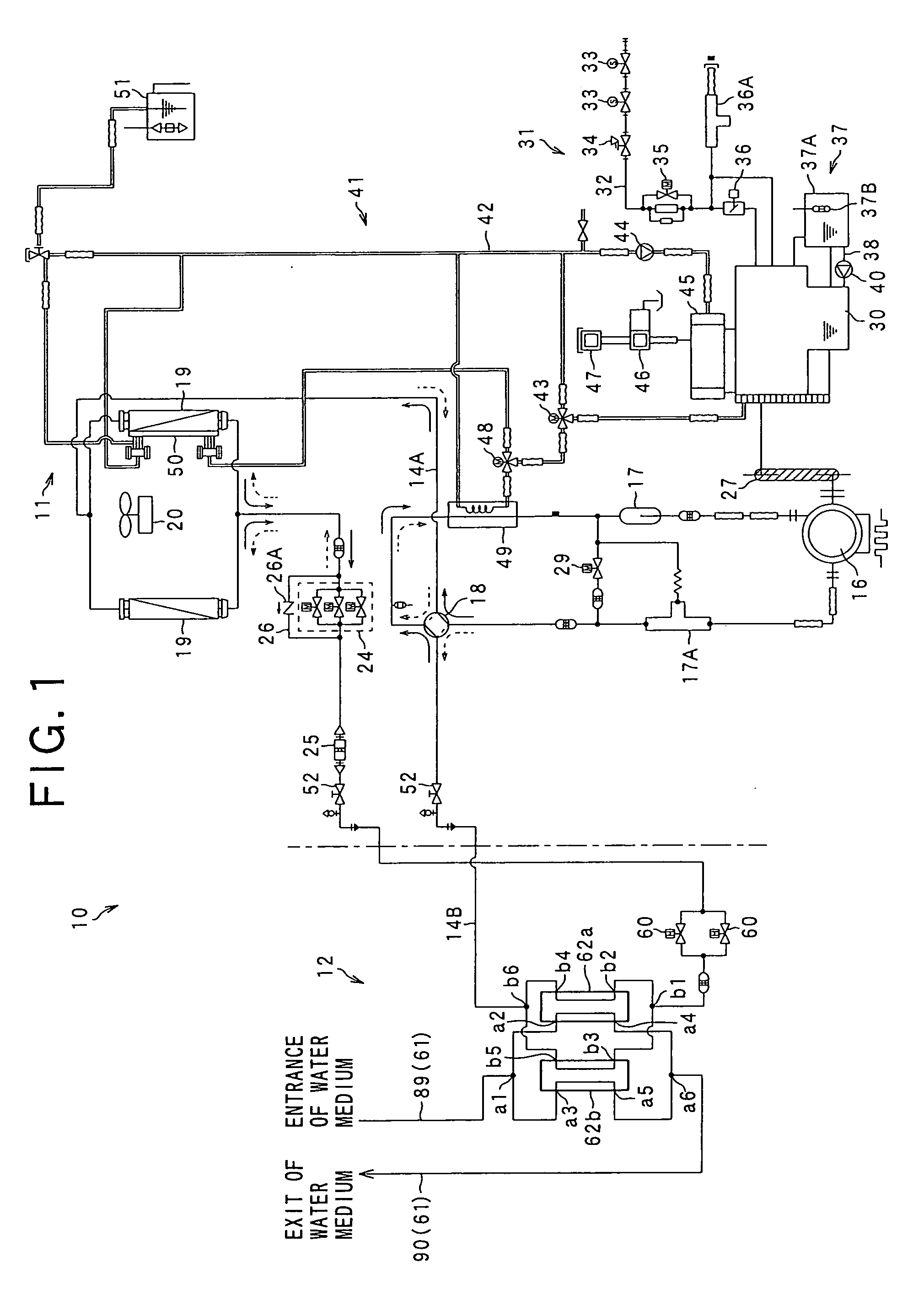
[0055]FIG. 1 is a refrigerant circuit diagram showing a refrigeration unit 10 having a chiller unit 12 according to a first embodiment.

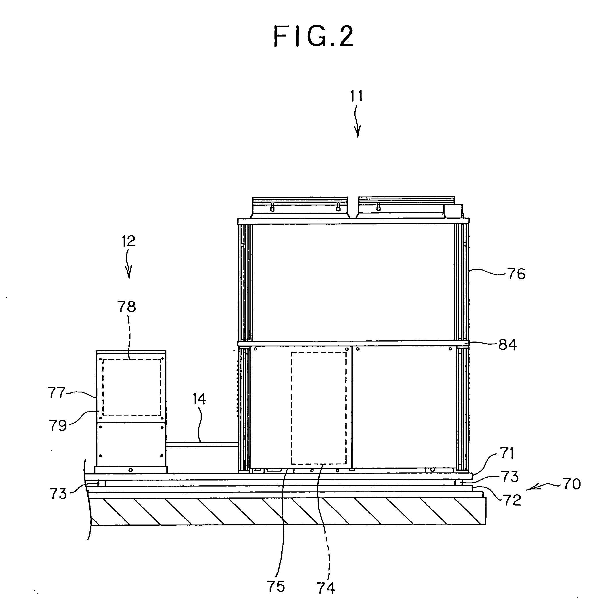
[0056]As shown in FIG. 1, the refrigeration unit 10 has an outdoor unit 11 and a chiller unit 12, and an outdoor refrigerant pipe 14A of the outdoor unit 11 and a chiller-side refrigerant pipe 14B of the chiller unit 12 are joined to each other through closing valves 52, 53, thereby forming a refrigeration cycle 10A. In the following description, the outdoor refrigerant pipe 14A and the chiller-side refrigerant pipe 14B are generically referred to as “refrigerant pipe 14” unless there are specifically distinguished from each other.

[0057]A compressor 16 is disposed in the outdoor refrigerant pipe 14A of the outdoor unit 11. The compressor 16 is driven through a V belt 27 by a gas engine 30. An accumulator 17 is disposed at the suction side of the compressor 16, and a four-way valve 18 is disposed through an oil separator 17A at the discharge side of t...

second embodiment

[0110]In the above-described first embodiment, the chiller unit 12 has the two electrically-operated valves and the two plate type heat exchangers. However, the numbers of the electrically-operated valve and the plate type heat exchangers are not limited to those of the above embodiment, and these numbers may be set to three or more. In the following description, an embodiment of the chiller unit 12 having three electrically-operated valves and three plate type heat exchangers will be described.

[0111]In the description of this embodiment, the same constituent elements as the first embodiment are represented by the same reference numerals, and the description thereof is omitted.

[0112]FIG. 10 is a refrigerant circuit diagram showing a refrigerating machine 10 having the chiller unit 12 according to this embodiment.

[0113]In the chiller unit 12 of this embodiment, three electrically-operated valves 60 are provided in parallel with respect to the chiller-side refrigerant pipe 14B as show...

third embodiment

[0123]In the following embodiment, three chiller units are connected to one outdoor unit. FIG. 13 is a schematic diagram showing the construction of a refrigeration system 101a having a water medium pipe 114 of plural systems according to a third embodiment of the preset invention.

[0124]As shown in FIG. 13, the refrigeration system 101a has an outdoor unit 110, and three chiller units 111a, 111b, 111c are connected to the outdoor unit 110 in parallel through a single-system refrigerant pipe 128. The refrigeration system 101a also has the water medium pipe 114 of two systems, that is, a first-system water medium pipe 112 and a second-system water medium pipe 113. In FIG. 13, the chiller units 111a, 111b and 111c serve as refrigerant circuits which are set to generate cold water. The refrigeration system 101 under this state will be described hereunder.

[0125]As shown in FIG. 13, the outdoor unit 110 has an accumulator 115 for separating refrigerant into gas refrigerant and liquid refr...


PUM


Abstract

A chiller unit including a chiller unit main body connected to a refrigeration cycle, a plate type heat exchanger unit that is secured to an upper stage portion of the chiller unit main body and divided into plural plate type heat exchangers, and a pipe group having a water medium pipe and a refrigerant pipe for supplying water medium and refrigerant to each of the plate type heat exchangers while branching the water medium and the refrigerant and collectively disposed at a lower stage portion of the chiller unit main body, wherein at least an exit side portion of the water medium pipe is routed substantially horizontally along the bottom portion of the chiller unit main body and a flow switch is provided in a horizontally-extending pipe portion of the water medium pipe.

Description

INCORPORATION BY REFERENCE[0001]The present application claims priority under 35 U.S.C. §119 to Japanese Patent Application No. 2008-079696 filed on Mar. 26, 2008, Japanese Patent Application No. 2008-082626 filed on Mar. 27, 2008 and Japanese Patent Application No. 2008-082627 filed on Mar. 27, 2008. The content of the applications is incorporated herein by reference in its entirety.BACKGROUND OF THE INVENTION[0002]1. Field of the Invention[0003]The present invention relates to a chiller unit (apparatus) having a heat exchanger for performing the heat exchange between refrigerant and water medium, a refrigeration system having the chiller unit and an air conditioner having the chiller unit.[0004]2. Description of the Related Art[0005]A chiller unit (apparatus) having a chiller unit main body connected to a refrigeration cycle is generally known (for example, JP-A-2004-251486). In this type of chiller unit, plural divided plate type heat exchangers are secured to the bottom portion ...

Claims


Application Information

Patent Timeline
IPC IPC(8): F25D23/00F28F3/08G05D23/00G05B15/00
CPCF25B13/00F25B41/003F25B47/006F25D17/02F25B2313/0233F25B2313/02741F25B2500/01F25B2313/003F25B27/00F25B40/06F25B49/005F25B49/02F25B2313/021F25B2313/0253F25B2313/0314F25B2327/001F25B2700/2106F25B2700/21173F25B2700/21175F24F11/42
Inventor FUKUSHIMA, MICHIOFUJIKAWA, HIDEKIYOSHII, SHIGERUKANAZAWA, SATORU
Owner PANASONIC INTELLECTUAL PROPERTY MANAGEMENT CO LTD
Why Eureka
Try Eureka