Liquid treatment apparatus, air conditioning system, and humidifier

a technology of liquid treatment apparatus and humidifier, which is applied in the direction of machine/engine, combustible gas purification/modification, and energy-based chemical/physical/physicochemical processes. it can solve the problems of limited power and durability of the power to sterilize bacteria in the condensed water and the air conditioning system, and achieve the effect of effectively oxidatively decomposing pollutants, high purification power, and effective destruction of bacteria

Inactive Publication Date: 2009-10-01
DAIKIN IND LTD
View PDF6 Cites 6 Cited by
  • Summary
  • Abstract
  • Description
  • Claims
  • Application Information

AI Technical Summary

Benefits of technology

[0033]In the present invention, electric discharge is generated towards the treatment target liquid (32a) emitted from the ejector (32), whereby active species generated in association with the generation of the electric discharge are absorbed in the treatment target liquid (32a). Consequently, in accordance with the present invention, it becomes possible to effectively destroy bacteria present in the treatment target liquid (32a). In addition, it becomes possible to effectively oxidatively decompose pollutants present in the treatment target liquid (32a). Accordingly, the liquid treatment apparatus of the present invention has extremely high purification power against the treatment target liquid (32a).
[0034]In addition, the electric discharge is generated directly to the treatment target liquid (32a), which makes it possible to physically destroy the bacteria in the treatment target liquid (32a) by the force of impact of the electric discharge. Accordingly, it becomes possible to enhance the bacteria sterilization power of the liquid treatment apparatus.
[0035]Especially, in the second aspect of the present invention, streamer discharge occurs from the discharge electrode (31) to the treatment target liquid (32a). The amount of generation of active species by the streamer discharge is greater as compared to other types of electric discharges, thereby making it possible to enhance the power to sterilize bacteria in the treatment target liquid (32a) and the power to purify the treatment target liquid (32a).
[0036]In addition, when a streamer discharge occurs from the discharge electrode (31) towards the treatment target liquid (32a), a current of ionic wind is produced in the same direction as the direction of the streamer discharge. In the second aspect of the present invention, the efficiency of gas-liquid contact between the active species and the treatment target liquid (32a) is improved by the ionic wind, whereby the active species are efficiently absorbed in the treatment target liquid (32a). Therefore, in accordance with the present invention, the purification power of the liquid treatment apparatus can be enhanced to a further extent.
[0037]Furthermore, in the third aspect of the present invention, the fine granular liquid droplets (32a) are emitted from the ejector (32) and an electric discharge is generated to the liquid droplets (32a). Consequently, in accordance with the third aspect of the present invention, the occurrence of electric sparking is prevented by the action of an air gap created between each liquid droplet (32a), whereby the electric discharge can be stabilized. Therefore, in accordance with the third aspect of the present invention, the amount of generation of active species is stabilized, whereby the purification power of the liquid treatment apparatus can also be stabilized.
[0038]In addition, in the third aspect of the present invention, the fine, granular liquid droplets (32a) contact with the active species. Therefore, in accordance with the third aspect of the present invention, the active species are easily absorbed in the liquid droplets (32a), whereby the power to purify the treatment target liquid (32a) can be enhanced to a further extent.

Problems solved by technology

In the case where, as in the patent document, the condensate water is treated with the aid of ultraviolet light, there are limits to the power to sterilize bacteria in the condensate water and the power to purify the condensate water and, in addition, there is the possibility that the air conditioning system will have to grow in size because the size of the ultraviolet irradiation unit is large.
However, there are limits to the durability of the power to sterilize bacteria, and it is impossible to ensure the quality of the condensate water for long periods.

Method used


Image

  • Liquid treatment apparatus, air conditioning system, and humidifier
  • Liquid treatment apparatus, air conditioning system, and humidifier
  • Liquid treatment apparatus, air conditioning system, and humidifier

Examples


first embodiment

of the Invention

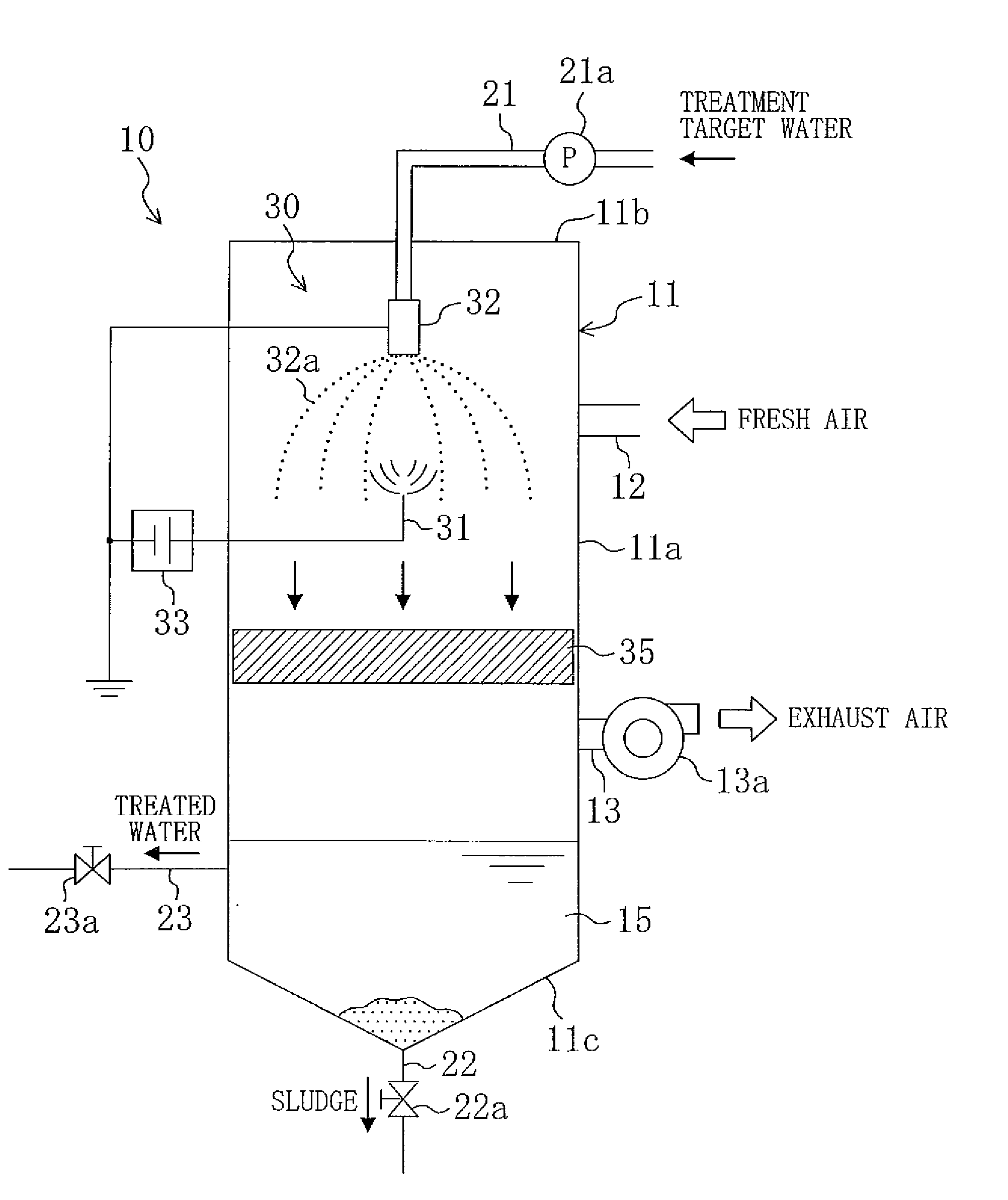
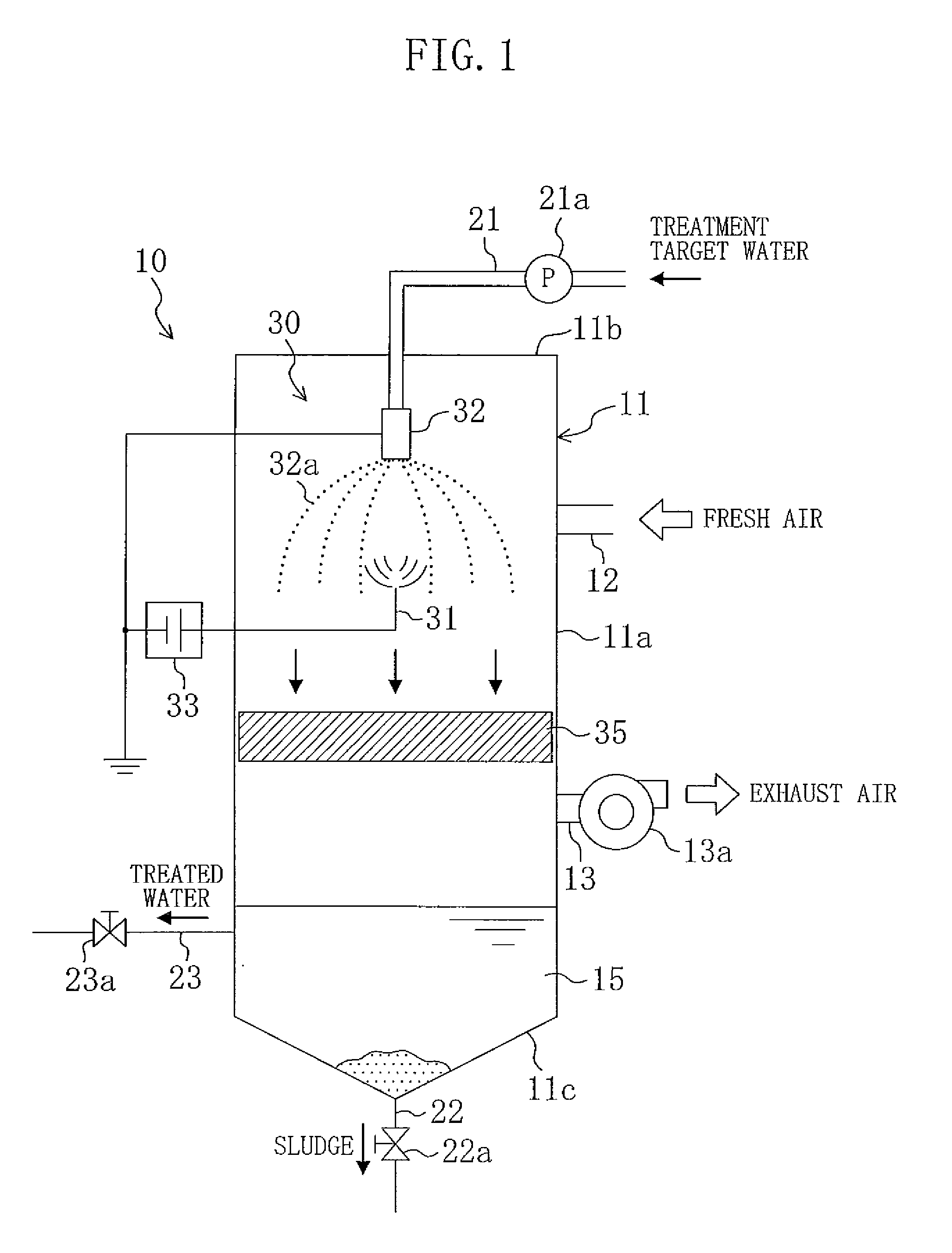
[0077]A liquid treatment apparatus (30) according to a first embodiment of the present invention finds application in a water treatment system (10) which is intended for the treatment of treatment target liquid (treatment target water) such as industrial treatment target water, sewage water et cetera.

[0078]As illustrated in FIG. 1, the water treatment system (10) is provided with a hollow, vertically-elongated liquid treatment tower (11). The liquid treatment tower (11) is composed of a body (11a) shaped like a circular cylinder, a top plate (11b) formed on the upper end of the body (11a), and a bottom plate (11c) shaped like a circular cone and projecting downwardly from the body (11a). In addition, a reaction tank (15) in which to temporarily store treatment target water is formed in the bottom of the liquid treatment tower (11).

[0079]The liquid treatment tower (11) is provided, in the side of the body (11a), with an air supply opening (12) and an air exhaust openi...

second embodiment

of the Invention

[0106]A liquid treatment apparatus (30) according to a second embodiment of the present invention is of the type that is mounted in an indoor unit (41) of an air conditioning system (40) for performing air conditioning of an indoor space. This indoor unit (41) is formed by a wall type room air conditioner for general household usage.

[0107]Referring to FIG. 3, the indoor unit (41) has a horizontally-elongated, substantially semi-cylindrical indoor casing (41a). The indoor casing (41a) is provided with an air inlet opening (42) formed along substantially the upper half of the front side (which is the left-hand side in FIG. 3), and an air outlet opening (43) formed in the lower end. The air inlet opening (42) constitutes an air introduction opening for the taking-in of indoor air into the indoor casing (41a). The air outlet opening (43) constitutes an air supply opening for the supply of air, temperature-controlled in the indoor unit (41), from within the indoor casing ...

third embodiment

of the Invention

[0124]A liquid treatment apparatus (30) according to a third embodiment of the present invention is of the type that is mounted in an outdoor unit (51) of an air conditioning system (40) for performing air conditioning of an indoor space.

[0125]As illustrated in FIG. 7) the air conditioning system (40) has a wall type indoor unit (41). The indoor unit (41) includes, as in the second embodiment, a prefilter, an indoor heat exchanger, a fan and so on (which are not shown in the figure). In addition, the air outlet opening of the indoor unit (41) is provided with a nozzle (61) for humidification whose details will be described later. That is, the air conditioning system (10) of the third embodiment is formed of an air conditioning system equipped with a humidification unit (humidifier).

[0126]In the other hand, the outdoor unit (51) is arranged outdoors. The outdoor unit (51) is connected to the indoor unit (41) via interunit piping (40a) through which the refrigerant flo...


PUM

PropertyMeasurementUnit
grain diameteraaaaaaaaaa
electric potentialaaaaaaaaaa
shapeaaaaaaaaaa

Abstract

In a liquid treatment apparatus, a discharge electrode (31) and an ejector (32) are arranged face to face with each other. An electric power supply (33) establishes an electric potential difference between the discharge electrode (31) and the ejector (32). As a result, a streamer discharge occurs from the discharge electrode (31) towards liquid droplets (32a) emitted from the ejector (32). Active species produced in association with the generation of the streamer discharge are absorbed in the liquid droplets (32a), whereby the treatment target water (32a) is sterilized and purified.

Description

TECHNICAL FIELD[0001]The present invention relates to a liquid treatment apparatus for the treatment of liquid. This invention further relates to an air conditioning system and to a humidifier, both of which incorporate therein such a liquid treatment apparatus.BACKGROUND ART[0002]Liquid treatment apparatuses of the type that are used for, for example, the purification of treatment target liquids have been widely known in the art. For example, JP-A-2004-108685 (hereinafter referred to as the “patent document”) discloses a liquid treatment apparatus for the purification of condensate water recovered in a drain pan of an air conditioning system.[0003]The air conditioning system of this patent document is provided, in its indoor unit, with a heat exchanger. Air to be treated is cooled in the heat exchanger, as a result of which moisture contained in the air condenses and condensate water is produced. In view of this, such a type of air conditioning system is provided, under the heat ex...

Claims


Application Information

Patent Timeline
Patent Type & Authority Applications(United States)
IPC IPC(8): F24F3/14C02F1/467B01F3/04F25D21/14
CPCC02F1/4608F24F2203/1032F24F2006/006F24F13/222B01J19/08C02F1/48F24F6/00F24F13/22
Inventor MOTEGI, KANJIODO, TSUNAHIROTANAKA, TOSHIOAKIYAMA, RYUJI
Owner DAIKIN IND LTD
Why Eureka
Try Eureka