Nonmagnetic Material Particle Dispersed Ferromagnetic Material Sputtering Target

a ferromagnetic material and non-magnetic material technology, applied in the direction of electrolysis components, vacuum evaporation coatings, coatings, etc., can solve the problems of inferior sputtering efficiency, high cost of rf (radio frequency) sputtering devices, large power consumption, etc., to achieve favorable sputtering efficiency, fast deposition speed, and superior

Active Publication Date: 2009-10-01
JX NIPPON MINING& METALS CORP
View PDF7 Cites 51 Cited by
  • Summary
  • Abstract
  • Description
  • Claims
  • Application Information

AI Technical Summary

Benefits of technology

[0028]As described above, the regulated target yields a superior effect of being able to be used in DC sputtering, and, in comparison to RF sputtering, DC sputtering has fast deposition speed and favorable sputtering efficiency. In addition, a DC sputtering device is advantageous in that it is inexpensive, easy to control, and has low power consumption.
[0029]Therefore, by using the sputtering target of the present invention, it is possible to obtain a high-quality material, and in particular a superior effect is yielded in

Problems solved by technology

Nevertheless, not only is the RF (radio frequency) sputtering device expensive, it possesses numerous drawbacks such as inferior sputtering efficiency, large power consumption, complex control and slow deposition speed.
If high power is applied to increase the deposition speed, the substrate temperature will rise, and there is a problem in that this will cause deterioration in the substrate and deposition material.
Even if the target possesses conductive property, if such target contains

Method used


Image

  • Nonmagnetic Material Particle Dispersed Ferromagnetic Material Sputtering Target
  • Nonmagnetic Material Particle Dispersed Ferromagnetic Material Sputtering Target
  • Nonmagnetic Material Particle Dispersed Ferromagnetic Material Sputtering Target

Examples


example 1

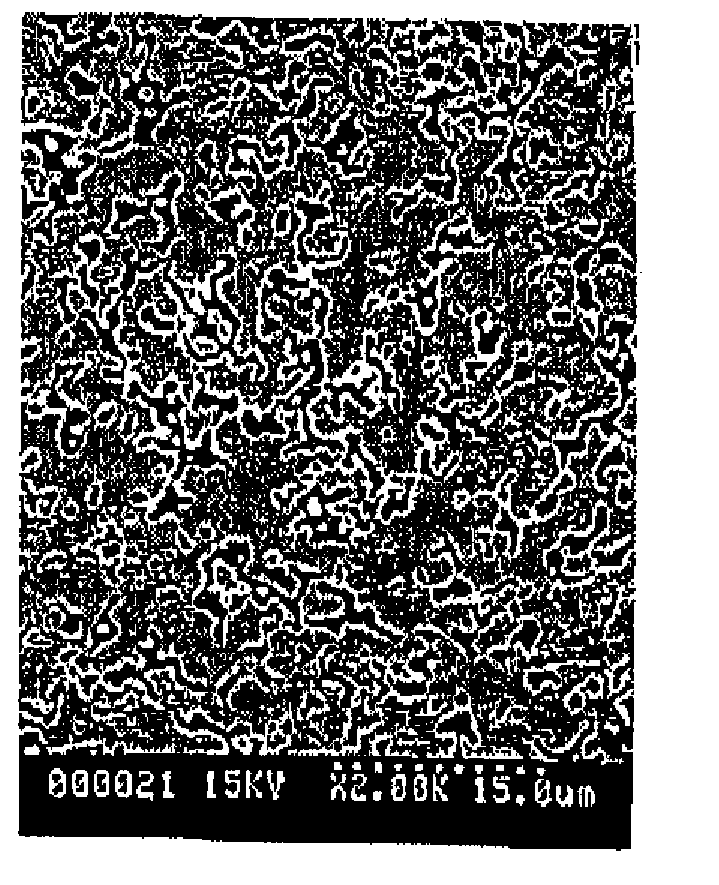
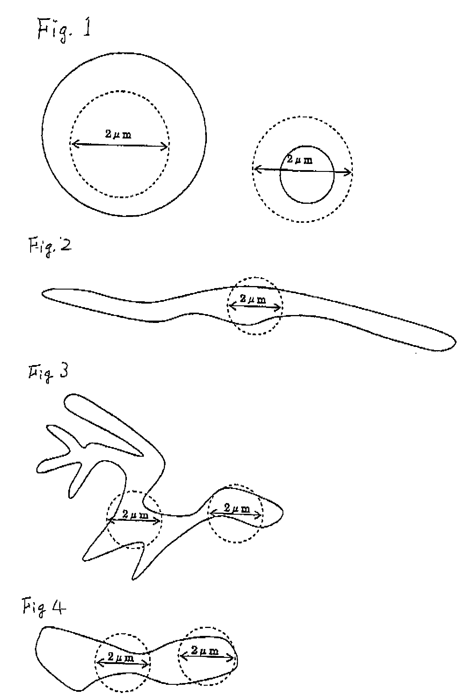
[0054]As sintering raw material powder, a magnetic material of Co fine powder, Cr fine powder, and Pt fine powder respectively having a grain size that is less than 5 μm was used, and at the same time SiO powder having an average grain size of 1 μm was used. This was weighed to achieve 94(74Co-10Cr-16Pt)-6SiO2 (mol %), and mixed in a wet ball mill for 100 hours. Subsequently, the mixed powder was filled in a carbon mold, and sintered with the hot press method at 1200° C. for 1 hour to obtain a ferromagnetic body material target composed of 94(74Co-10Cr-16Pt)-6SiO2.

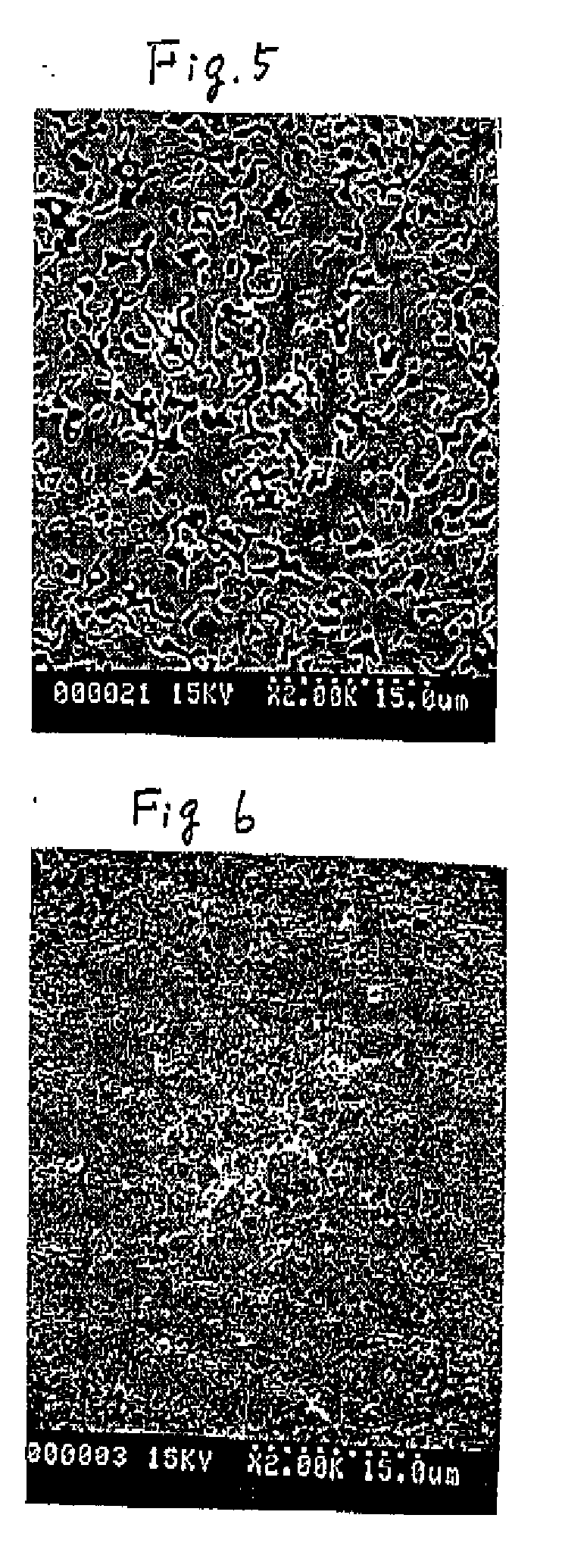
[0055]The relative density of this target was 98%, and a high density target was obtained. The results are shown in Table 1. The SEM image of the polished face of the target is shown in FIG. 5. As shown in FIG. 5, thin thread-shaped fine SiO2 particles were dispersed therein.

[0056]The distance from an arbitrary point in the SiO2 particles as the nonmagnetic material to the interface upon drawing a perpendicular line toward...

example 2

[0059]As sintering raw material powder, a magnetic material of Co fine powder, Cr fine powder, and Pt fine powder respectively having a grain size that is less than 5 μm was used, and at the same time Ta2O5 powder having an average grain size of 1 μm was used. This was weighed to achieve 97(74Co-10Cr-16Pt)-3Ta2O5 (mol %), and mixed in a ball mill for 60 hours. Subsequently, the mixed powder was filled in a carbon mold, and sintered with the hot press method at 1200° C.; for 1 hour to obtain a ferromagnetic body material target composed of 97(74Co-10Cr-16Pt)-3Ta2O5 (mol %).

[0060]The relative density of this target was 98%, and a high density target was obtained. The results are shown in Table 1. The SEM image of the polished face of the target is shown in FIG. 6. As shown in FIG. 6, simulated spherical fine Ta2O5 particles were dispersed therein.

[0061]The distance from an arbitrary point in the Ta2O5 particles as the nonmagnetic material to the interface upon drawing a perpendicular ...

example 3

[0064]As sintering raw material powder, a magnetic material of Co fine powder, Cr fine powder, and Pt fine powder respectively having a grain size that is less than 5 μm was used, and at the same time commercially available Cr2O3 powder having an average grain size of 1 μm was used. This was weighed to achieve 94(74Co-10Cr-16Pt)-8 Cr2O3 (mol %), and mixed in a ball mill for 100 hours. Subsequently, the mixed powder was filled in a carbon mold, and sintered with the hot press method at 1200° C. for 1 hour to obtain a ferromagnetic body material target composed of 94(74Co-10Cr-16Pt)-8Cr2O3 (mol %).

[0065]The relative density of this target was 98%, and a high density target was obtained. The results are shown in Table 1. The SEM image of the polished face of the target is shown in FIG. 7. As shown in FIG. 71 thin thread-shaped fine Cr2O3 particles were dispersed therein.

[0066]The distance from an arbitrary point in the Cr2O3 particles as the nonmagnetic material to the interface upon d...


PUM

PropertyMeasurementUnit
Diameteraaaaaaaaaa
Diameteraaaaaaaaaa
Sizeaaaaaaaaaa

Abstract

Provided is a nonmagnetic material particle dispersed ferromagnetic material sputtering target comprising a material including nonmagnetic material particles dispersed in a ferromagnetic material. The nonmagnetic material particle dispersed ferromagnetic material sputtering target is characterized in that all particles of the nonmagnetic material with a structure observed on the material in its polished face have a shape and size that are smaller than all imaginary circles having a radius of 2 μm formed around an arbitrary point within the nonmagnetic material particles, or that have at least two contact points or intersection points between the imaginary circles and the interface of the ferromagnetic material and the nonmagnetic material. The nonmagnetic material particle dispersed ferromagnetic material sputtering target is advantageous in that, in the formation of a film by sputtering, the influence of heating or the like on a substrate can be reduced, high-speed deposition by DC sputtering is possible, the film thickness can be regulated to be thin, the generation of particles (dust) or nodules can be reduced during sputtering, the variation in quality can be reduced to improve the mass productivity, fine crystal grains and high density can be realized, and the nonmagnetic material particle dispersed ferromagnetic material sputtering target is particularly best suited for use as a magnetic recording layer.

Description

TECHNICAL FIELD[0001]The present invention relates to a nonmagnetic material particle dispersed ferromagnetic material sputtering target, and in particular relates to a nonmagnetic material particle dispersed ferromagnetic material sputtering target which realizes, in the formation of a film by sputtering, stable direct current (DC) sputtering and optimal deposition speed, minimal arcing during the sputtering, reduction in the particles (dust) and nodules caused by such arcing, high density, minimal variation in quality, and improvement of mass productivity.BACKGROUND ART[0002]In the field of magnetic recording, technology has been developed for improving the magnetic property by causing a nonmagnetic material to coexist in a magnetic body thin film. Some of the examples are technology for improving the soft magnetic property such as magnetic permeability by causing fine particles of the nonmagnetic material to exist in the magnetic material thin film, and technology for improving v...

Claims


Application Information

Patent Timeline
IPC IPC(8): C23C14/34
CPCC23C14/3414H01F41/183G11B5/851
Inventor SATOH, KAZUYUKI
Owner JX NIPPON MINING& METALS CORP
Why Eureka
Try Eureka