Laser diode assemblies

a technology of laser diodes and assemblies, applied in semiconductor lasers, instruments, optical elements, etc., can solve the problems of reducing the coupling efficiency between reducing the coupling efficiency of laser diodes and optical fibers, and underutilizing the input area of fibers, so as to reduce misalignment and high heat conductivity

Inactive Publication Date: 2009-10-01
FAYBISHENKO VICTOR
View PDF24 Cites 118 Cited by
  • Summary
  • Abstract
  • Description
  • Claims
  • Application Information

AI Technical Summary

Benefits of technology

[0006]Some embodiments of the present invention help reduce misalignments caused by heat and by mechanical pressures generated in attaching a laser diode assembly to other components, e.g. to a “cold plate” (a plate cooled via active cooling, e.g. by liquid or air or by a thermo-electric cooler).
[0009]Given this structure, it is also desirable to lengthen the beam path so as to reduce the numerical aperture (NA) of the combined beam (the beam stack) entering the optical fiber. The reduced NA increases the combined beam's brightness and also facilitates fitting the combined beam into the fiber's acceptance angle. In some embodiments, the beam path is increased by extending the beam along at least three sides of a square (or a rectangle) running along the assembly periphery. For example, in some embodiments, the laser diodes are positioned in a row along a “first side” of the square. In a Cartesian coordinate system with an X axis positioned along this first side, the laser diodes emit beams propagating along a YZ plane. Here X and Y are horizontal axes and Z is vertical. The Y axis provides the second side of the square path. The beams are collimated in their fast and slow axes as they travel along the YZ plane, i.e. along the second side. The collimating lenses are immediately followed by turning mirrors which turn the respective beams by about 90° to travel along the third side of the square. The beams are at different heights to form the beam stack. As soon as the beam stack is formed, i.e. immediately past the X coordinate of the last laser diode (or its submount), the beam stack hits another turning mirror. This turning mirror turns the beam stack by about 90° to travel along the square's fourth side. This turning mirror is immediately followed by a focusing optics that focuses the beam stack into the optical fiber's input. A highly compact structure is thus provided.

Problems solved by technology

Therefore, direct coupling of the output beam into the fiber is inefficient, underutilizing the fiber's input area and hence the fiber's capacity for input brightness and power.
Even minute misalignments between the laser diodes and the optical components (such as turning mirrors and the collimating and focusing optics) may reduce the coupling efficiency between the laser diodes and the optical fiber.

Method used


Image

  • Laser diode assemblies
  • Laser diode assemblies
  • Laser diode assemblies

Examples


Embodiment Construction

[0017]The embodiments described in this section illustrate but do not limit the invention. The invention is defined by the appended claims.

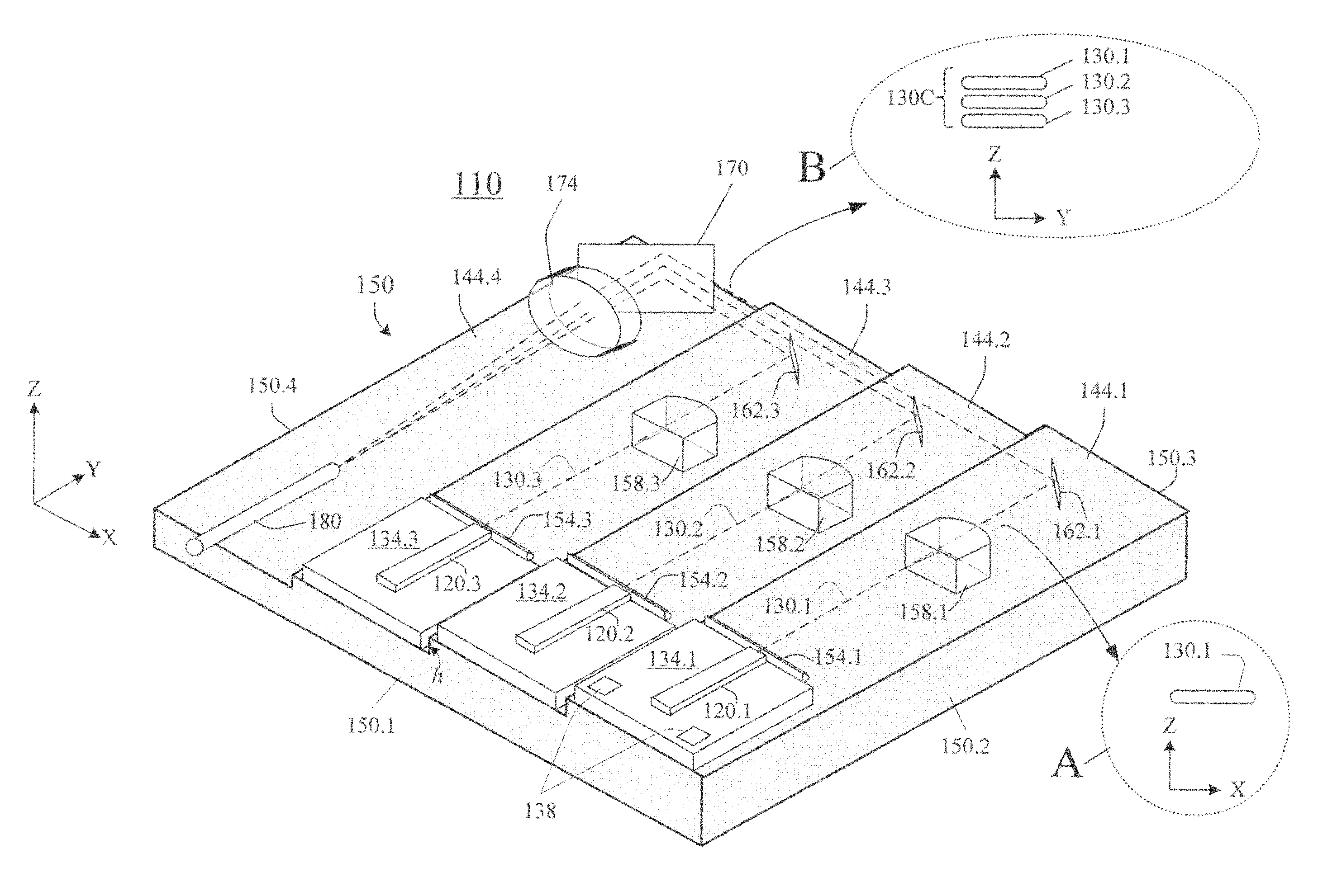
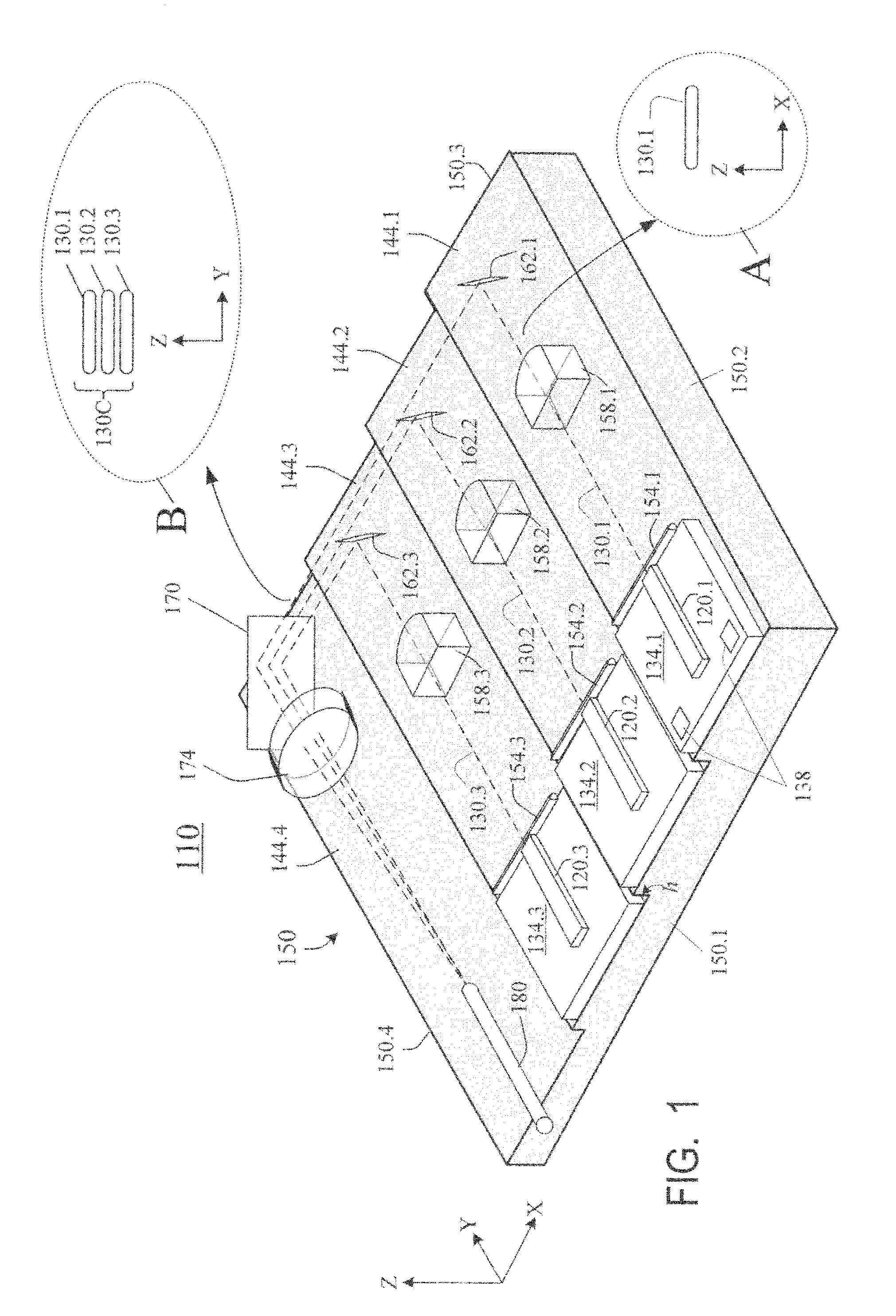
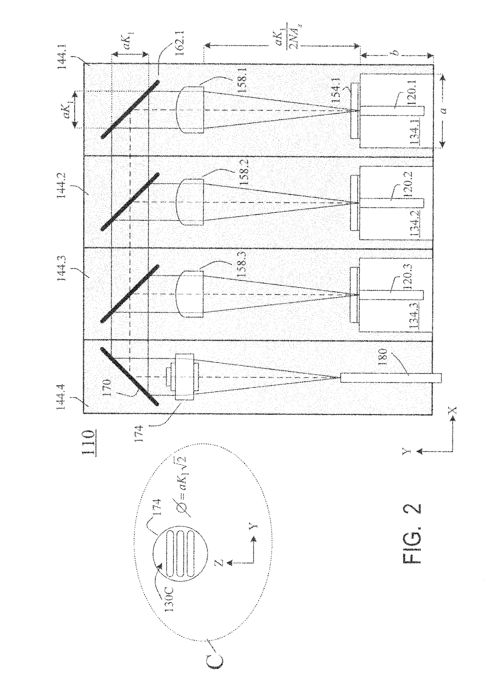
[0018]FIG. 1 is a perspective view of a laser diode assembly 110 according to some embodiments of the present invention. FIG. 2 is a top view of the assembly. FIG. 3 is a perspective view of assembly 110 with packaging used in some embodiments. The assembly will be described with reference to a Cartesian coordinate system XYZ where X and Y are horizontal axes and Z is vertical. However, the invention is not limited by any coordinate system, and further the assembly 110 can be oriented and operated in any position.

[0019]Assembly 110 includes three laser diodes 120.1, 120.2, 120.3 laterally spaced from each other in the X direction. Any number of diodes can be present. In this embodiment, each diode 120.i (i=1, 2, 3) is a single-emitter diode, formed in a discrete semiconductor structure, but this is not necessary for the invention. Diodes 120 have...


PUM

PropertyMeasurementUnit
angleaaaaaaaaaa
anglesaaaaaaaaaa
angleaaaaaaaaaa

Abstract

Laser diodes (120) emit laser beams along a vertical YZ plane at different distances from the YZ plane. The beams are collimated in their fast and slow axes, and are redirected by turning mirrors (162) to form a beam stack (130C) traveling along the XZ plane. The beam stack is turned by about 90°, then converged by a focusing lens (174) into an optical fiber (180). A compact assembly is thus provided. Each laser diode (120.i), its collimating optics (154.i, 158.i, i=1, 2, . . . ) and its turning mirror (162.i) are rigidly attached to a flat, heat-spreading surface (144.i) and thus remain aligned with each other in thermal cycling.

Description

BACKGROUND OF THE INVENTION[0001]The present invention relates to laser diode assemblies.[0002]Laser diodes offer both high output power and a small footprint, making them good candidates for many applications including materials processing, medical devices, telecommunications, printing, and other uses. The output of the laser diode can be coupled to an optical fiber serving as a waveguide or providing a laser cavity for a fiber laser. The optical fiber's input surface is typically circular, while the laser diode's output beam is roughly an elongated rectangle. Therefore, direct coupling of the output beam into the fiber is inefficient, underutilizing the fiber's input area and hence the fiber's capacity for input brightness and power.[0003]To increase the brightness and power coupled into the fiber, output beams of multiple laser diodes can be stacked above each other (i.e. with the long axes stacked above each other) to more closely approximate a circle. The long axis of a laser d...

Claims


Application Information

Patent Timeline
Patent Type & Authority Applications(United States)
IPC IPC(8): H01S5/40
CPCG02B6/4206G02B6/4214H01S5/005Y10T29/49002H01S5/02252H01S5/02284H01S5/4012H01S5/02248H01S5/02326H01S5/02325H01S5/02251
Inventor FAYBISHENKO, VICTOR
Owner FAYBISHENKO VICTOR
Why Eureka
Try Eureka