Misalignment Prevention in an External Cavity Laser Having Temperature Stabilisation of the Resonator and the Gain Medium

a laser and external cavity technology, applied in the direction of lasers, optical resonator shape and construction, semiconductor lasers, etc., can solve the problems of reducing the performance of lasers, reducing wavelength stability, and reducing wavelength accuracy over the entire tuning range, so as to avoid the creation of relatively large fluctuations in laser output optical power

Active Publication Date: 2009-10-08
GOOGLE LLC
View PDF8 Cites 18 Cited by
  • Summary
  • Abstract
  • Description
  • Claims
  • Application Information

AI Technical Summary

Benefits of technology

[0044]The present invention has the advantage that compensation of the variations of the optical path length of the laser cavity due to mechanical deformations is carried out passively, without the need of introducing an active thermal control and / or an extra electronic control circuit.
[0045]It is to be noted that compensation of the variation of the optical path length of the laser cavity according to the present invention can be also partial, i.e., in the direction of a significant decrease of said variation without reducing it to zero. Also when partial compensation is achieved by the present solution, it will be possible to achieve full compensation by making only small adjustments of the injection current of the gain medium, thereby avoiding creation of relatively large fluctuations in the laser output optical power. Preferably, injection current adjustments are within about ±10 mA and more preferably within ±5 mA.

Problems solved by technology

As DWDM uses narrower channel spacing, wavelength (frequency) accuracy of transmitter lasers over the entire tuning (e.g., the C-band) and operating temperature range has become an important issue.
Spatial misalignments of optical components of the laser device may arise from temperature variations due to expansions and contractions associated to the various components, which will reduce wavelength stability and generally reduce the performance of the laser.
Because an optical bench is typically supported on the top surface of a TEC, this may lead to deformation of the optical bench itself.

Method used


Image

  • Misalignment Prevention in an External Cavity Laser Having Temperature Stabilisation of the Resonator and the Gain Medium
  • Misalignment Prevention in an External Cavity Laser Having Temperature Stabilisation of the Resonator and the Gain Medium
  • Misalignment Prevention in an External Cavity Laser Having Temperature Stabilisation of the Resonator and the Gain Medium

Examples


Embodiment Construction

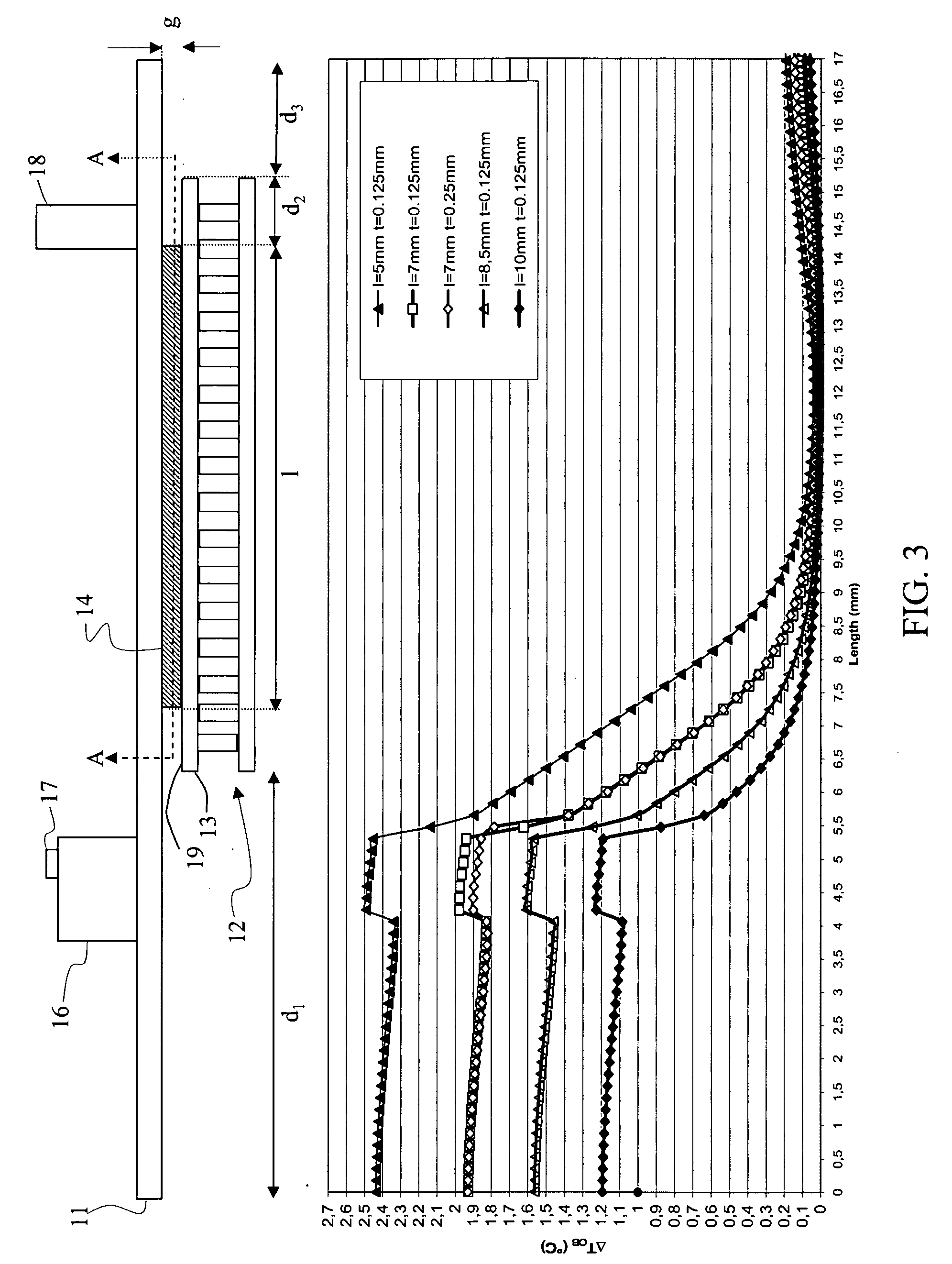
[0056]FIG. 3 shows results from computer simulations (by using a finite-element analyser) of the temperature curves, i.e., temperature variation, ΔTOB, vs. position along the length of an optical bench mounting a laser assembly, wherein ΔTOB=(TOB−T1) and TOB is the temperature measured on the optical bench upper surface. The upper part of the figure schematically illustrates (not to scale) the configuration of the laser module considered in computer simulations. Optical bench 11 is placed on a TEC 12 with surface area of the thermally stabilised surface 19 of 12.2×7 mm2, i.e., the TEC upper carrier plate 13 is a rectangular-shaped plate having a main longitudinal direction along the X-axis, said surface being stabilised at a temperature T1=25° C. Simulations are carried out at an environmental temperature of Tenv=70° C., i.e., ΔT=45° C. The optical bench 11 is a rectangular-shaped plate of length of 17 mm along the longitudinal main direction of the optical bench (i.e., the X axis),...


PUM


Abstract

The present invention relates to an external-cavity laser module comprising a thermoelectric cooler (TEC) including an upper carrier plate having an upper surface, said TEC being configured to stabilise the temperature of the upper surface at a substantially constant temperature. The laser module further comprises a laser assembly mounted on an optical bench, which is in thermal coupling with said upper surface, said laser assembly comprising a gain medium for emitting an optical beam into the external cavity and an end mirror.

Description

[0001]The invention relates to an external-cavity laser and in particular to an external cavity tuneable laser that is especially adapted as optical transmitter for wavelength-division multiplexed optical communication networks.RELATED ART[0002]The use of lasers as tuneable light source can greatly improve the reconfigurability of wavelength-division multiplexed (WDM) systems or of the newly evolved dense WDM (DWDM) systems. For example, different channels can be assigned to a node by simply tuning the wavelength. Also, tuneable lasers can be used to form virtual private networks based on wavelength routing, i.e., photonic networks.[0003]Different approaches can be used to provide tuneable lasers, such as distributed Bragg reflector lasers, VCSEL lasers with a mobile top mirror, or external-cavity diode lasers. External-cavity tuneable lasers offer several advantages, such as high output power, wide tuning range, good side mode suppression and narrow linewidth. Various laser tuning ...

Claims


Application Information

Patent Timeline
Patent Type & Authority Applications(United States)
IPC IPC(8): H01S3/04
CPCH01S3/0815H01S3/105H01S3/1062H01S5/005H01S5/0064H01S5/141H01S5/02284H01S5/02415H01S5/02438H01S5/0654H01S5/06837H01S5/02248H01S5/02325H01S5/02251
Inventor ROSSI, GIACOMO ANTONIOGRASSI, SERGIO WALTER
Owner GOOGLE LLC
Why Eureka
Try Eureka