Plasma discharge treatment apparatus, and method of manufacturing gas barrier film

a discharge treatment and gas barrier technology, applied in the field ofplasma discharge treatment, can solve the problems of insufficient gas barrier ability, inability to apply in fields demanding a high level of gas barrier, and inability to observe content from the outside, so as to reduce surface failure, reduce scratches and defects, and improve the effect of yield

Inactive Publication Date: 2009-10-08
KONICA MINOLTA INC
View PDF6 Cites 27 Cited by
  • Summary
  • Abstract
  • Description
  • Claims
  • Application Information

AI Technical Summary

Benefits of technology

[0039]The first object according to the foregoing Structures 1-10 of the present invention is to provide a manufacturing apparatus by which obtained can be a highly-functional film advantageous over before in view of cost, mass-production and quality, since the production system is simplified so as to use the minimum number of rollers brought into contact with the film forming surface, and the yield is improved because of reduction of scratches and defects on the film forming surface or the surface-modified surface.
[0040]Further, the second object according to the foregoing Structures 11-15 of the present invention is to provide a method of preparing a gas barrier film exhibiting high gas barrier, together with reduction of surface failure (crack failure) during gas barrier thin layer formation.

Problems solved by technology

Aluminum foils have been widely utilized as the packaging material in such the fields, but in addition to a problem of disposal after use, it is not basically transparent, and there is another problem such that no content can be observed from the outside.
On the other hand, a resin film made of a vinylidene chloride resin or a copolymer resin formed from vinylidene chloride and another polymer, or a material exhibiting gas barrier obtained by coating a vinylidene chloride based resin onto a polypropylene resin, a polyester resin or a polyamide resin has been widely utilized as the packaging material, but there presently appears a problem in view of environmental conservation since chlorine based gas is generated in the course of incineration disposal.
However, gas barrier ability has been insufficient yet, and can not be applied for fields demanding a high level of gas barrier.
However, there is a problem such that a film substrate such as a transparent plastic film exhibits inferior gas barrier to that of a glass substrate.
When a substrate exhibiting inferior gas barrier is employed as a substrate for an organic EL element, an organic layer is degraded because of permeation of water vapor and the air, resulting in deterioration of emission characteristics, durability and so forth.
Further, when a polymer substrate is employed as a substrate for electronic devices, also produced is a problem such that oxygen permeates the polymer substrate, and penetrates into the inside of the electronic device to diffuse it, whereby the device is deteriorated, and a vacuum degree desired in the inside of the device can not be maintained.
However, when gas barrier thin layers composed of an adhesion layer, a ceramic layer and a protective layer, for example, are multilayered on a flexible plastic film, cracks and fracture of thin layers tend to be generated during conveyance in the case of a low flexible layer comparatively brittle against stress among the formed layers.
As the result, cracks and fracture of the thin layer are generated in comparatively brittle gas barrier layers formed on the plastic film, whereby it is clearly confirmed that the gas barrier property largely drops.

Method used


Image

  • Plasma discharge treatment apparatus, and method of manufacturing gas barrier film
  • Plasma discharge treatment apparatus, and method of manufacturing gas barrier film
  • Plasma discharge treatment apparatus, and method of manufacturing gas barrier film

Examples


example

Example 1

[0558]Examples in which gas barrier films were prepared employing a plasma discharge treatment apparatus of the present invention according to any one of Structures 1-6.

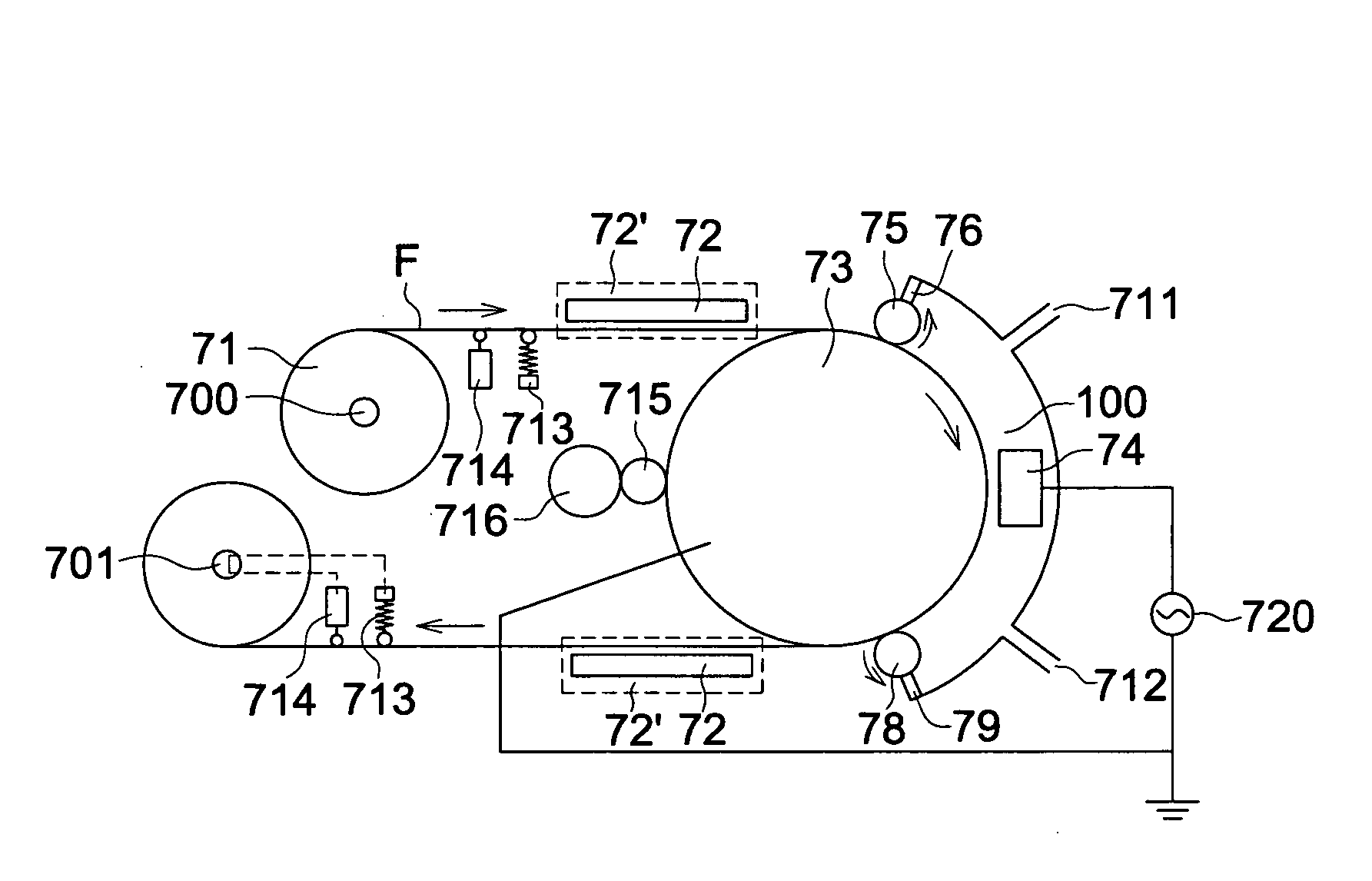
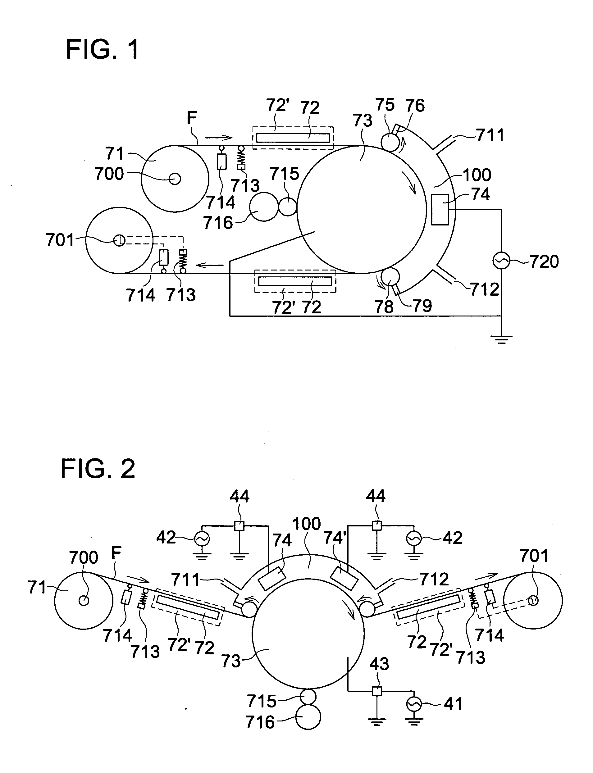
[0559]The treatment was carried out employing the plasma discharge treatment apparatus shown in FIG. 2, and a thin film was formed on a substrate by introducing raw material and electric power into each electrode section.

[0560]A dielectric of a thickness of 1 mm was coated on facing electrodes via a thermally sprayed ceramic treatment. The spacing between electrodes was also set to 1 mm. A metal base material on which a dielectric was coated was prepared in accordance to the stainless jacket specification having a cooling function with cooling water, and the plasma discharge treatment was conducted while controlling electrode temperature with cooling water during discharging. Power supplies used here were a high frequency power supply (80 kHz) manufactured by Oyo Electric Co., Ltd., and a high frequency powe...

example 2

[0583]Examples in which gas barrier films were prepared employing a plasma discharge treatment apparatus of the present invention according to any one of Structures 7-10.

[0584]Thin layers were formed on a substrate in order as described below by introducing each raw material and power into each electrode section with a plasma discharge treatment apparatus shown in FIG. 5.

[0585]A dielectric of a thickness of 1 mm was coated on facing roll electrodes via a thermally sprayed ceramic treatment. The spacing between electrodes was also set to 1 mm. A metal base material on which a dielectric was coated was prepared in accordance to the stainless jacket specification having a cooling function with cooling water, and the plasma discharge treatment was conducted while controlling electrode temperature with cooling water during discharging. Power supplies used here were a high frequency power supply (80 kHz) manufactured by Oyo Electric Co., Ltd., and a high frequency power supply (13.56 MHz)...

example 3

Preparation of Resin Film

[0609]A prepared actinic radiation curable resin layer coating solution having the following composition was coated on a PEC (polyethylene naphthalate) film (a width of 50 cm and a thickness of 125 μm) Q65, produced by Teijin DuPont Films Japan Ltd. as a resin substrate, employing a micro-gravure coater, so as to give a thickness of 6 μm after curing. After the solvent is vaporized and dried, a polymer film comprising an acrylic curable layer was formed by curing via a UV exposure of 0.2 J / cm2 employing a high-pressure mercury lamp.

(Actinic radiation curable resin layer coating solution)Dipenta erythritol hexaacrylate monomer60parts by weightDipenta erythritol hexaacrylate dimmer20parts by weightDipenta erythritol hexaacrylate trimer20parts by weightDimethoxybenzophenone photoreaction4parts by weightInitiatorMethylethyl ketone75parts by weightPropylene glycol monomethylether75parts by weight

>

[Preparation of Sample 1]

[0610]A 50 nm thick adhesion film, a 30 nm...


PUM

PropertyMeasurementUnit
curvature radiusaaaaaaaaaa
RHaaaaaaaaaa

Abstract

Provide is a method of preparing a highly-functional film capable of reducing surface failure and of improving the yield, and a manufacturing apparatus thereof. This is a plasma discharge treatment apparatus to plasma-discharge-treat for the surface of a substrate conveyed between a winder and an unwinder at atmospheric pressure or approximately atmospheric pressure, and is a plasma discharge treatment apparatus by which the substrate is conveyed with no contact by only nip roller separating the discharge section from outside. Provided is a method of preparing a gas barrier film exhibiting high gas barrier, together with reduction of surface failure (crack failure) during gas barrier thin layer formation. The surface on the gas barrier thin layer side of the gas barrier film has a curvature radius of at least 75 mm during conveyance, and the surface on the opposite side has a curvature radius of at least 37.5 mm.

Description

TECHNICAL FIELD[0001]The present invention relates to a plasma discharge treatment method and an apparatus thereof to form a thin layer first on the substrate via plasma discharge treatment and to conduct a substrate surface-modifying treatment, and specifically to a plasma discharge treatment method and a plasma discharge treatment apparatus suitable for preparing highly-functional film substrates utilized for displays such as a liquid crystal display, an organic electroluminescence display, a plasma display and so forth by forming a thin layer specifically on a long length substrate film and conducting a surface-modifying treatment with no performance degradation generated by defects caused by surface scratches and pressure. Further, the present invention relates to a method of manufacturing a gas barrier film exhibiting high gas barrier, together with reduction of surface failure (crack failure) during gas barrier thin layer formation in preparation of the gas barrier film obtain...

Claims


Application Information

Patent Timeline
Patent Type & Authority Applications(United States)
IPC IPC(8): C23C16/50C23C16/54
CPCC23C16/45595H01J37/3277C23C16/545C23C16/517
Inventor OZAKI, KOJIFUKUDA, KAZUHIROARITA, HIROAKI
Owner KONICA MINOLTA INC
Why Eureka
Try Eureka