Anode and secondary battery
a secondary battery and anode technology, applied in the field of secondary batteries, can solve the problems of increasing electric power consumption and reducing cycle characteristics, and achieve the effects of reducing cycle characteristics, high performance and increasing electric power consumption
- Summary
- Abstract
- Description
- Claims
- Application Information
AI Technical Summary
Benefits of technology
Problems solved by technology
Method used
Image
Examples
example 1-1
[0199]The laminated film secondary battery illustrated in FIG. 8 and FIG. 9 was fabricated by the following procedure. The secondary battery was fabricated as a lithium ion secondary battery in which the capacity of the anode 54 was expressed based on insertion and extraction of lithium.
[0200]First, the cathode 53 was formed. First, lithium carbonate (Li2CO3) and cobalt carbonate (COCO3) were mixed at a molar ratio of 0.5:1. After that, the mixture was fired in the air at 900 deg C. for 5 hours. Thereby, lithium cobalt complex oxide (LiCoO2) was obtained. Subsequently, 91 parts by mass of the lithium cobalt complex oxide as a cathode active material, 6 parts by mass of graphite as a cathode electrical conductor, and 3 parts by mass of polyvinylidene fluoride as a cathode binder were mixed to obtain a cathode mixture. After that, the cathode mixture was dispersed in N-methyl-2-pyrrolidone to obtain paste cathode mixture slurry. Finally, both faces of the cathode current collector 53A...
examples 1-2 to 1-11
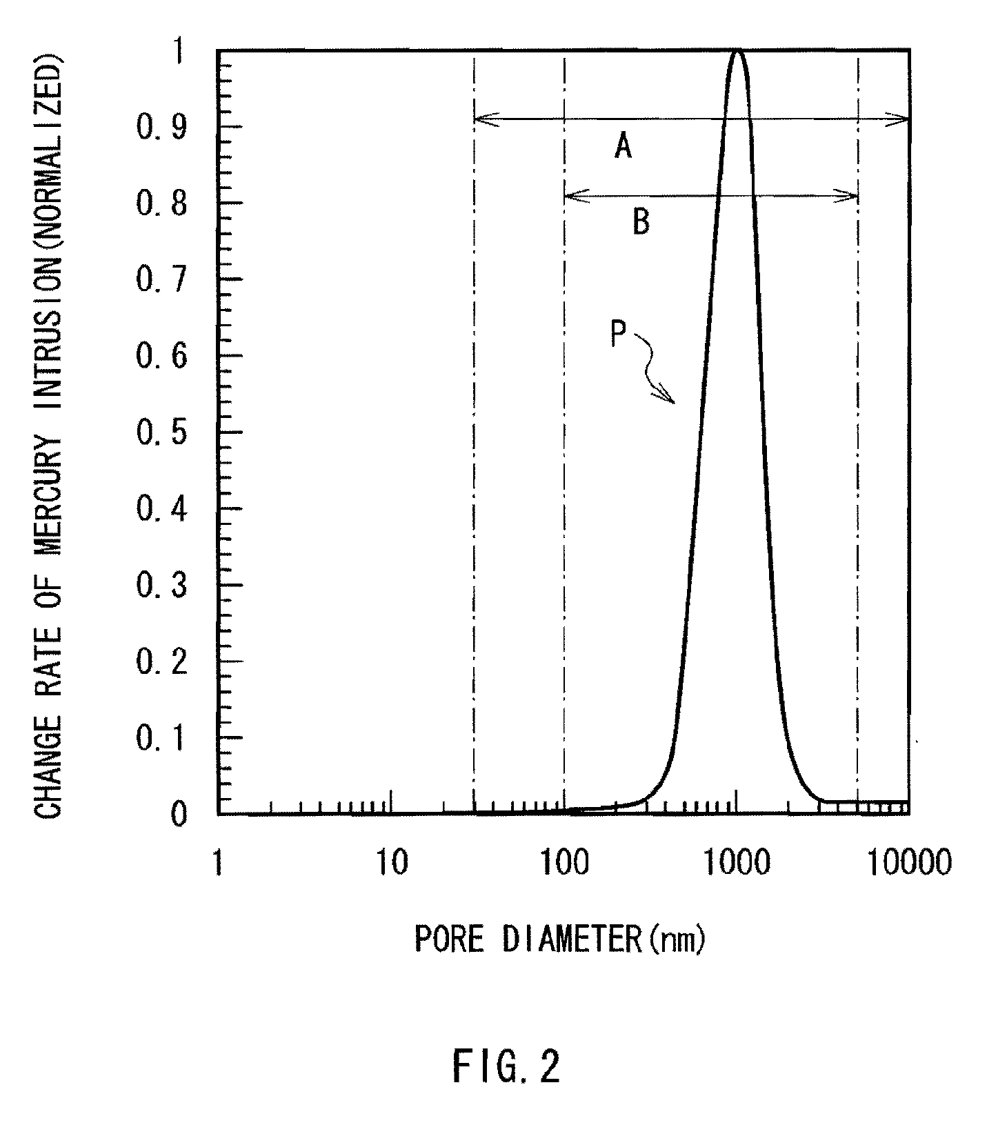
[0205]A procedure was performed in the same manner as that of Example 1-1, except that the pore diameter of the peak was changed to 50 μm (Example 1-2), 100 μm (Example 1-3), 200 μm (Example 1-4), 500 μm (Example 1-5), 700 μm (Example 1-6), 1000 μm (Example 1-7), 2000 μm (Example 1-8), 5000 μm (Example 1-9), 7000 μm (Example 1-10), or 10000 μm (Example 1-11). The pore diameter of the peak was changed by adjusting conditions such as the content of the anode binder in the anode active material layer 54B, the press pressure in compression molding, and heat treatment temperature.
examples 2-1 to 2-16
[0214]A procedure was performed in the same manner as that of Example 1-1, except that the change rate of mercury intrusion showed two peaks and the pore diameter of the two peaks were adjusted. Specifically, the pore diameters of the two peaks were 15 nm and 700 nm (Example 2-1), 25 nm and 1000 nm (Example 2-2), 100 nm and 500 nm (Example 2-3), 200 nm and 500 nm (Example 2-4), 100 nm and 700 nm (Example 2-5), 200 nm and 700 nm (Example 2-6), 100 nm and 1000 nm (Example 2-7), 150 nm and 1300 nm (Example 2-8), 500 nm and 1000 nm (Example 2-9), 700 nm and 6000 nm (Example 2-10), 900 nm and 1500 nm (Example 2-11), 1000 nm and 5000 nm (Example 2-12), 15 nm and 700 nm (Example 2-13), 100 nm and 500 nm (Example 2-14), 200 nm and 700 nm (Example 2-15), or 700 nm and 6000 nm (Example 2-16). The number of peaks and the pore diameter were changed by adjusting conditions such as the content of the anode binder in the anode active material layer 54B, the press pressure in compression molding, a...
PUM
| Property | Measurement | Unit |
|---|---|---|
| pore diameter | aaaaa | aaaaa |
| pore diameter | aaaaa | aaaaa |
| porosity | aaaaa | aaaaa |
Abstract
Description
Claims
Application Information
 - R&D
- Intellectual Property
- Life Sciences
- Materials
- Tech Scout
- Unparalleled Data Quality
- Higher Quality Content
- 60% Fewer Hallucinations
Browse by: Latest US Patents, China's latest patents, Technical Efficacy Thesaurus, Application Domain, Technology Topic, Popular Technical Reports.
© 2025 PatSnap. All rights reserved.Legal|Privacy policy|Modern Slavery Act Transparency Statement|Sitemap|About US| Contact US: help@patsnap.com


