Method and apparatus for minimally invasive implants

Inactive Publication Date: 2009-10-08
NOVALERT
View PDF3 Cites 54 Cited by
  • Summary
  • Abstract
  • Description
  • Claims
  • Application Information

AI Technical Summary

Benefits of technology

[0008]Provided are devices for minimally invasive delivery of implants and monitoring for the integrity of implants, such as breast implants, that function to alert the user or a healthcare provider that the integrity of the implant is failing. Methods of using these devices also are provided. The devices are useful for reducing surgical incisions, reducing recovery time and measuring leakage into or out of the implant as well as other parameters such as changes in electrical properties within the device.
[0009]One embodiment of the device includes hydrogel which will greatly decrease exposure to foreign materials (many hydrogels are over 90% water or saline) in the event of a rupture. The hydrogels of the present invention require a minimum of 80% water / saline in their hydrated state in order to allow for sufficient compression to provide a minimally invasive state. The hydrogel may be manufactured and compressed from its final, solid, hydrated three-dimensional form (similar to a compressed cellulose sponge) and / or may be a semisolid viscous gel similar in texture to silicone oil, then desiccated or dehydrated in order to provide for compression prior to delivery. The solid, cohesive hydrogel which consists of hydrophilic groups covalently bonded to each other, may be free-floating or preferably, bonded to the shell of the implant. Alternatively, the shell of the device may be formed by dipping the preformed expanded hydrogel into a silicone liquid or casting the shell around the preformed hydrogel. The hydrogel used in the present invention may include, but should not be limited to: Chitin, Mannuronic Acid, Guluronic Acid, Glucomannan, Hyaluronic acid, Chitosan, PEG, HPMC, Pluronic, PVA and / or glycerol derived polymers. Alternatively, the hydrogel may also consist of acrylate, polyethylene oxide, cellulose, collagen, acetic acid, or other polysaccharide derived polymer. Alternatively, the polymer may be any hydrophilic, biocompatible material capable of being compressed and expanded upon rehydration. In further alternative embodiments, the hydrogel may consist of coating on the inside of implant shell and / or a coating on a silicone support structure within the shell which provides a hydrophilic interface to the silicone supports or silicone shell.
[0010]Use of the hydrogel of the present invention allows for the possibility of inflation or expansion in situ due to the possibility of desiccation pre-implantation and hydration post-implantation. This is a key feature and an important aspect of the present invention in that the rehydration in situ allows for the implant to be packaged within an insertion pod and placed minimally invasively through a small incision in the umbilicus or lower breast much as is done with saline-filled implants today. Unlike saline-filled implants today, though, the hydrogel implants of the current invention have a far superior feel, comparable to that of silicone-gel filled implants. Thus, through 
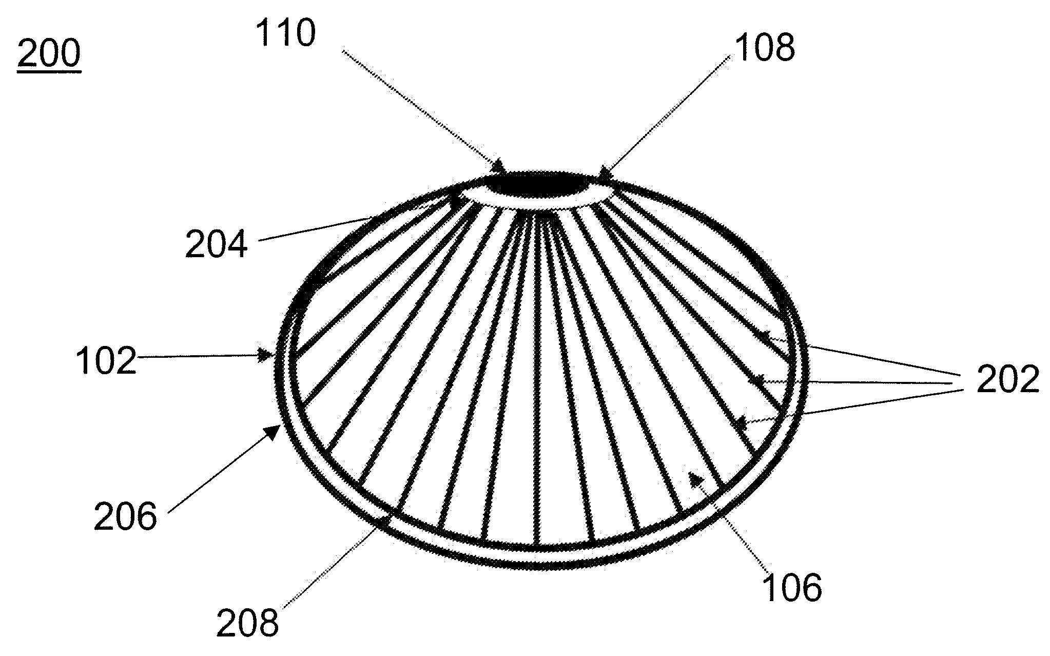
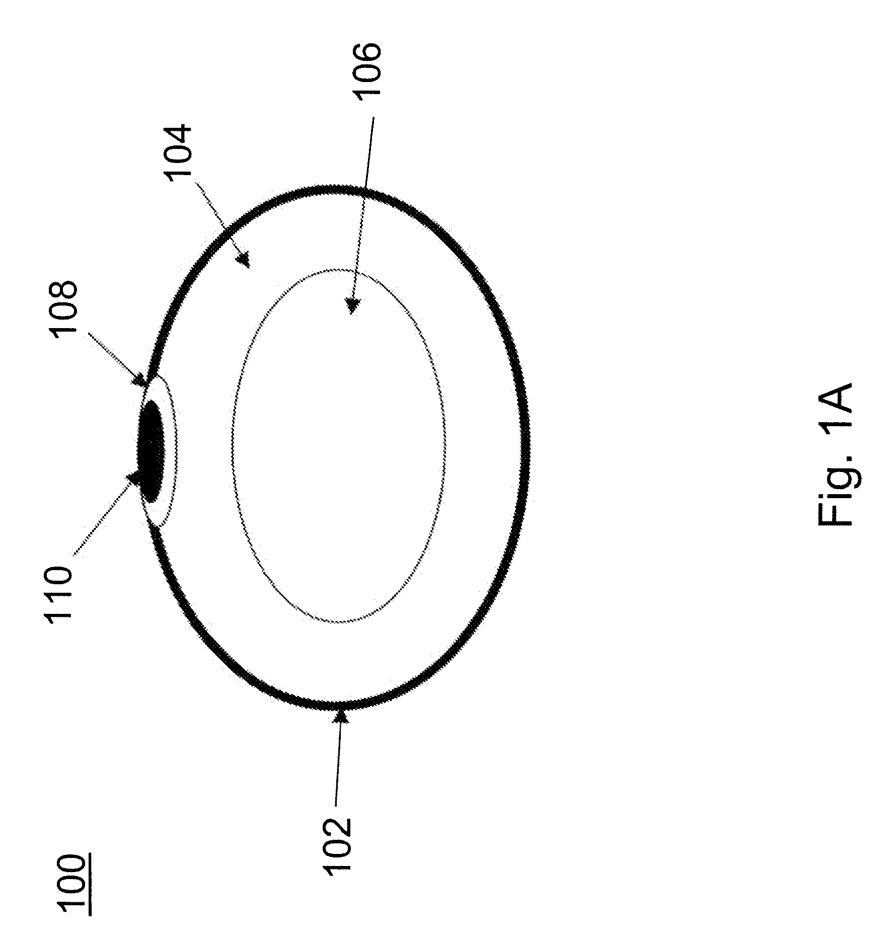
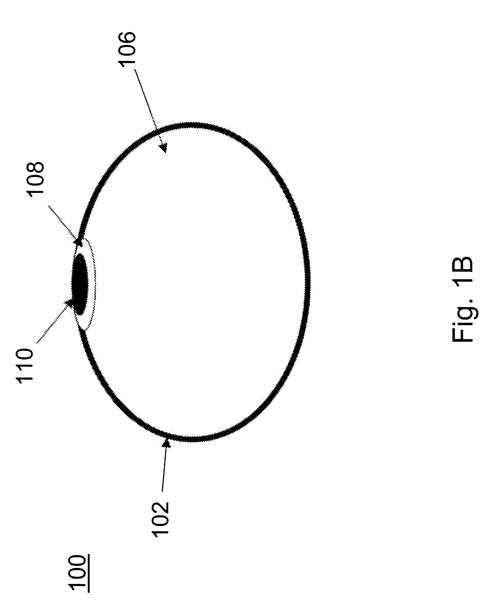
desiccation, compression, delivery, and rehydration of a hydrogel within a breast implant shell, the present invention provides the benefits of silicone-gel filled breast implant with the lower risks associated with a saline-filled implant. In its preferred embodiment, the hydrogel is created in its final shape covered by or inserted into a silicone shell and then desiccated and / or compressed after the patch, with rupture sensing capabilities as described below, affixed to the patch of the implant. This polymerization of the hydrogel followed by desiccation and cross-linking allows for a defined shape to the breast implant, a feature that is currently considered a main advantage of silicone implants over saline implants. Once the device is inserted into the body in its compressed state, it is then rehydrated using a water-based solution designed to create an isoosmolar environment within the implant. After rehydration, the filling line is removed from the implant and it assumes its final configuration.

Problems solved by technology

While silicone gel implants are capable of maintaining their shape and have a convincingly realistic “feel” (particularly important for breast implants), they require chemical curing and exposure to toxic chemicals which requires them to be fully manufactured and inflated prior to insertion.
Furthermore, exposure to these chemicals and materials constitutes a potential health hazard which resulted in the long-standing FDA ban on such materials in breast implants implemented in 1992 and still in effect.
Furthermore, due to the radiographic nature of the silicone shell and the silicone gel, it is also notoriously difficult to detect ruptures in silicone-filled implants.
This means that one quarter of all patients will have an incorrect reading of the status of their silicone filled breast implant.
A breach in the shell would decrease the resistance path due to loss of the insulating silicone layer and, over time, the influx of saline will further decrease the resistance path leading to an even bigger change in resistance that may be easily detected.
Thus, a rupture of the shell would result in the loss of two heavily insulating layers, silicone and titanium resulting in a larger change in the resistance detected.
With silicones, this exposure has been shown to create local inflammation and scarring, sometime severe enough to necessitate mastectomy, and silicones are suspected to cause other, more systemic problems as well.
If the shell of the implant ruptures, though, exposure of the hydrogel has been found to cause some problems, such as calcification of the hydrogel within the implant (along with the associated difficulty in interpreting mammograms) making it prudent to ensure rupture detection and device replacement.

Method used


Image

  • Method and apparatus for minimally invasive implants
  • Method and apparatus for minimally invasive implants
  • Method and apparatus for minimally invasive implants

Examples


Embodiment Construction

[0030]Presently preferred embodiments of the invention are illustrated in the drawings. An effort has been made to use the same, or like, reference numbers throughout the drawings to refer to the same or like parts.

[0031]The proposed implant monitoring device of this application serves as a solution to the issues of: 1) Providing minimally invasive insertion of implants with saline or aqueous fluid fillers while preventing deflation and / or migration, and 2) Monitoring for leakage from, or leakage into, implants (such as breast implants, pacemakers, implantable cardioverter defibrillators, other inflatable devices and other related devices). The device described herein has the ability to be inserted minimally invasively and to sense and communicate the occurrence of loss of integrity in the shell of virtually any implant.

[0032]The competitive advantages of the present invention include minimally invasive insertion with a safe aqueous filler while providing the feel of the less safe s...


PUM

PropertyMeasurementUnit
Hydrophilicityaaaaaaaaaa

Abstract

The present invention involves a device and method capable of providing minimally invasive insertion of implants with saline, aqueous or other fluid fillers while preventing deflation and / or migration, as well as monitoring for leakage from, or leakage into, implants (such as breast implants, pacemakers, implantable cardioverter defibrillators, other inflatable devices and other related devices). The device described herein has the ability to be inserted minimally invasively and to sense and communicate the occurrence of loss of integrity in the shell of virtually any implant.

Description

CROSS REFERENCE TO RELATED APPLICATION[0001]Priority is claimed to U.S. Provisional Patent Application Ser. No. 60 / 832,768, filed Jul. 24, 2006, the contents of which are incorporated herein by reference.FIELD OF THE INVENTION[0002]The present invention relates to the field of medical devices. In particular, the present invention relates to minimally invasive placement and monitoring of the integrity of liquid or gel-filled implants (such as breast implants) implanted within tissues or organs.BACKGROUND OF THE INVENTION[0003]The primary parts of most breast implants are a shell (also known as an envelope or lumen), a filler, and a patch to cover a manufacturing hole. Breast implants may vary in shell surface (e.g., smooth or textured), shape (e.g., round or other shape), profile (i.e., how far it projects), volume, area, and shell thickness. With respect to the shell design, while most breast implants are single lumen (i.e., one shell), some breast implants are double lumen (i.e., o...

Claims


Application Information

Patent Timeline
IPC IPC(8): A61F2/12
CPCA61B5/076A61B5/14539A61B5/14546A61B5/6846A61F2/12A61L27/52A61F2250/0003A61L27/18C08L83/02
Inventor BURNETT, DANIEL R.
Owner NOVALERT
Why Eureka
Try Eureka