Cellular systems with distributed antennas

a distributed antenna and cellular technology, applied in the field of cellular communication systems, can solve the problems of insufficient rationalization insufficient utilization of fiber optic trunk lines, so as to achieve efficient utilization of low-frequency wireless internet access bandwidth, efficient utilization of millimeter wave trunk lines, and efficient utilization of low-frequency bandwidth

Inactive Publication Date: 2009-10-15
TREX ENTERPRISES CORP
View PDF1 Cites 859 Cited by
  • Summary
  • Abstract
  • Description
  • Claims
  • Application Information

AI Technical Summary

Benefits of technology

[0025]High frequency antennas are described to maintain beam directional stability to less than one-half the half-power beam width. In the preferred embodiment where the spectral ranges are 71-76 GHz and 81-86 GHz, the half power beam width is about 0.4 degrees or less for a 2-foot antenna. The millimeter wave trunk line bandwidth is efficiently utilized over and over again by using transmitting antennae that are designed to produce very narrow beams directed at receiving antennae. The low frequency wireless internet access bandwidth is efficiently utilized over and over again by dividing a territory into s...

Problems solved by technology

However, the construction of fiber optic trunk lines is expensive (sometimes very expensive) and the design and the construction of these lines can often take many months especially if the route is over private property or produces environmental controversy.
Often the expected revenue from the potential users of a particular trunk line under consideration does not justify the cost of the fiber optic trunk line.
In conjunction with the above availability requirements, weather-related attenuation limits the useful range of wireless data transmission at all wavelengths shorter than the very long radio waves.
At the higher, millimeter-wave frequencies, (i.e., 30 GHz to 300 GHz corresponding to wavelengths of 1.0 centimeter to 1.0 millimeter) where available bandwidth is highest, rain attenuation in very bad weather limits reliable wireless link performance to distances of 1 mile or less.
People in the past have avoided use of their cellular equipment because the cost was higher that their line telephones.
The equipment in these remote cellular stations may be limited to an antenna for low frequency communication with user cellular equipment such as cell phones and other electronic communication equipment including PDA's and laptop computers and equipment for...

Method used


Image

  • Cellular systems with distributed antennas
  • Cellular systems with distributed antennas
  • Cellular systems with distributed antennas

Examples


Embodiment Construction

Back-Haul and Front-Haul

[0031]In a first preferred of the present invention described in detail in this application millimeter wave transceivers are used both as links to connect base stations to remote cellular station, referred to as “front-haul” communication and also to connect the base stations to a point of presence in an optical fiber communication network, referred to as “back-haul”.

BRIEF DESCRIPTION OF THE DRAWINGS

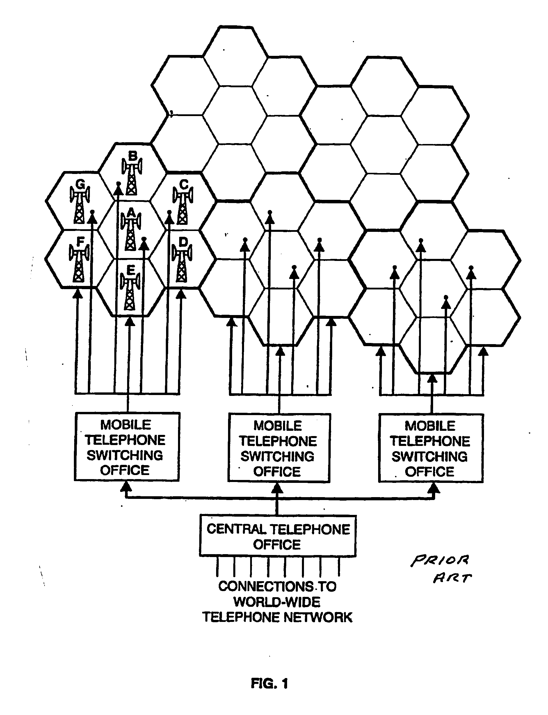
[0032]FIG. 1 is a sketch showing a prior art cellular network.

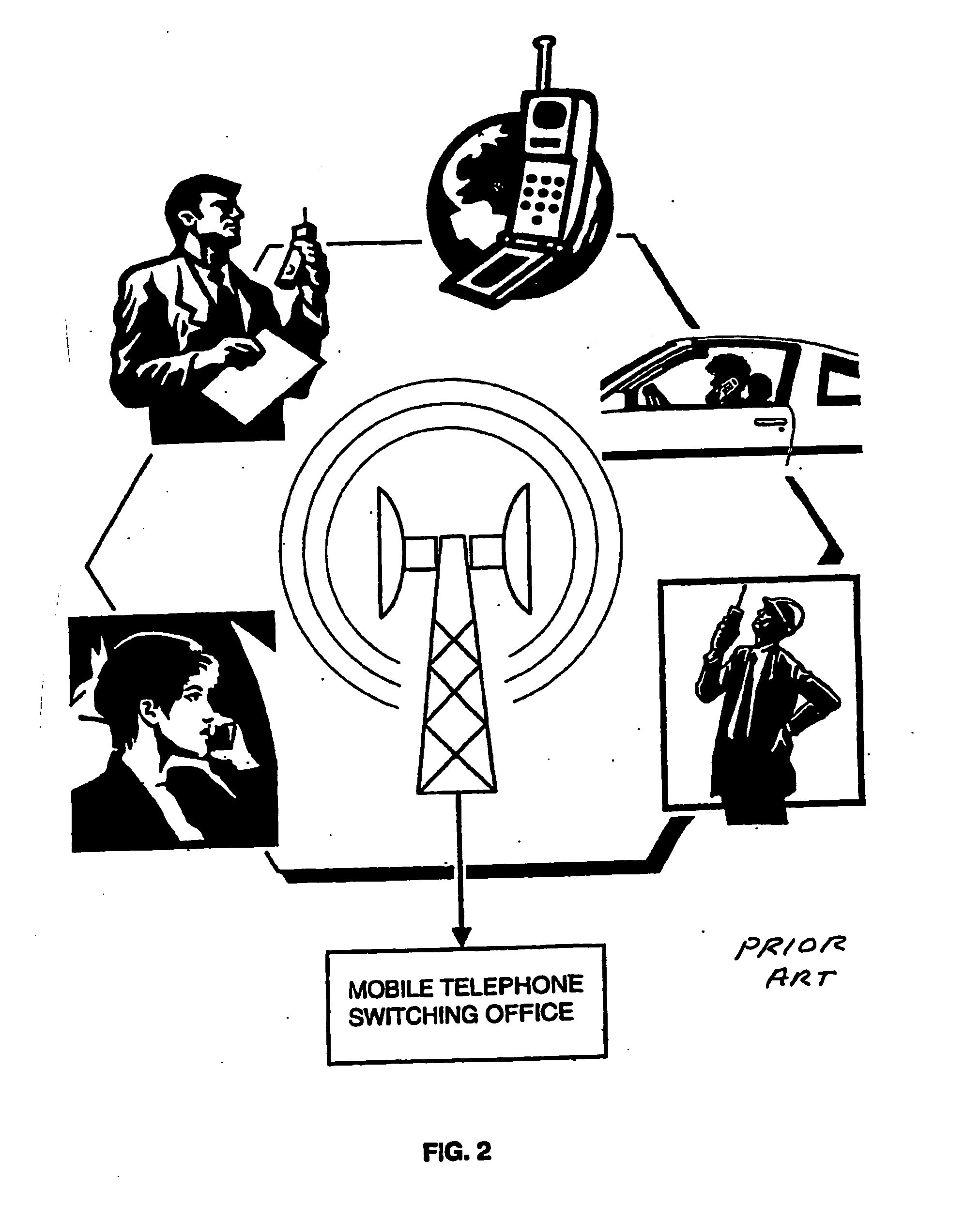
[0033]FIG. 2 is a sketch showing features of a single prior art cell.

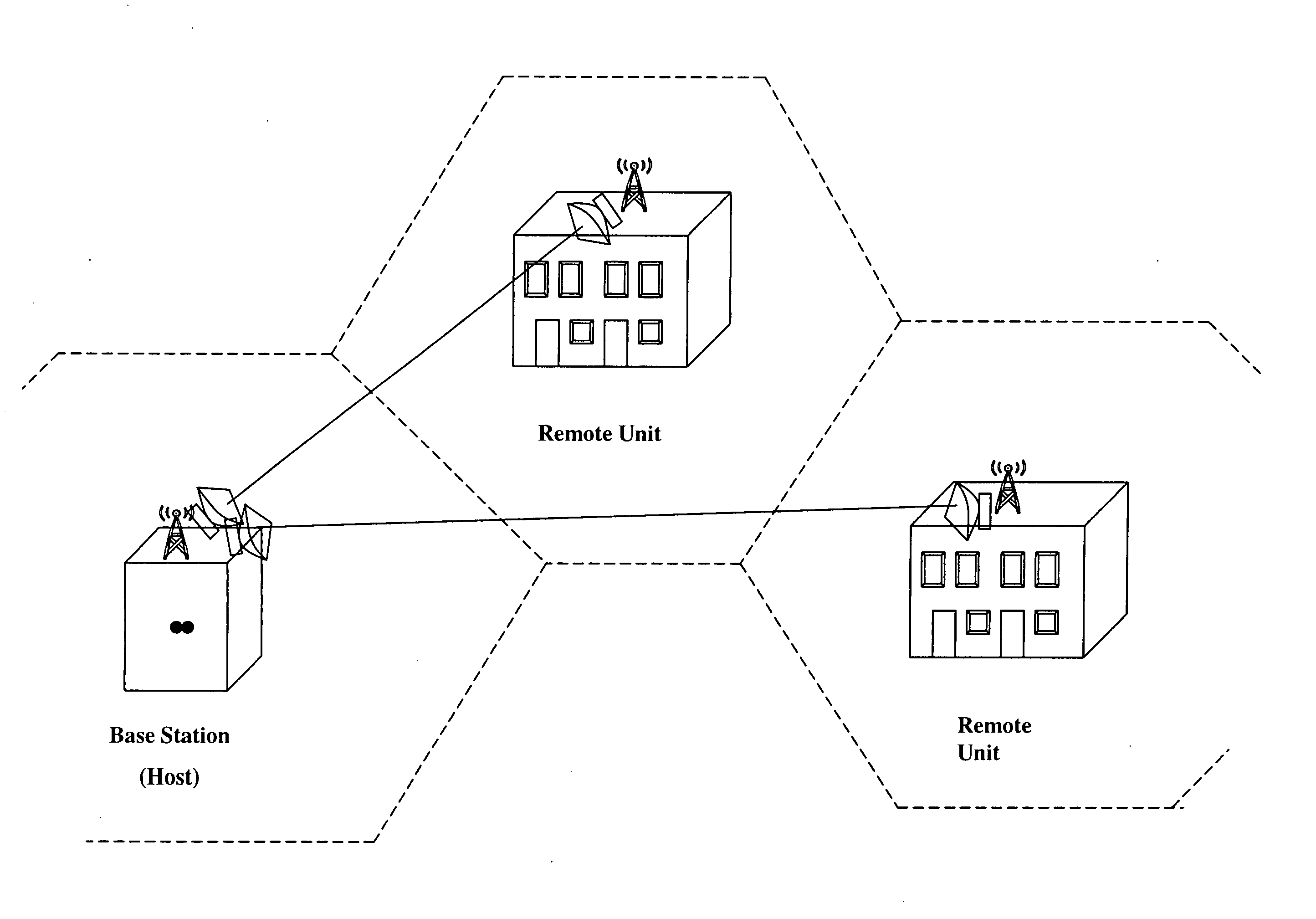
[0034]FIG. 3A is a sketch of a millimeter wave trunk line connecting cellular base stations.

[0035]FIG. 3B is a sketch of a millimeter wave trunk line connecting wireless internet access base stations.

[0036]FIG. 4A demonstrates up conversion from cell phone frequencies to trunk line frequencies.

[0037]FIG. 4B demonstrates up conversion from wireless internet access frequencies to trunk line frequencies

[0038]FIG. 5A demonstrates down conv...


PUM


Abstract

A communication system providing wireless communication among wireless users through a number of cellular base stations, each including at least transport management equipment and broadband equipment, at least one of which supports at least remote cellular station including RF equipment for communication with users of cellular devices. The system includes at lease one wireless narrow beam communication link operating at millimeter wave frequencies in excess of 60 GHz connecting a remote cellular station with a cellular base station equipped with broad band conversion electronic equipment and transport management equipment. In preferred embodiment the communication system includes a large number of remote cellular stations with each remote cellular station serving a separate communication cell. Each remote cellular station is equipped with a low frequency wireless transceiver for communicating with the wireless users within the cell at a radio frequency lower than 6 GHz and a narrow beam millimeter wave wireless transceiver operating at a millimeter wave frequency higher than 60 GHz for communicating with another millimeter wave transceiver at another remote cellular station or a millimeter wave transceiver at a base station.

Description

CROSS REFERENCE TO RELATED APPLICATIONS[0001]This invention is a continuation in part application of U.S. patent application Ser. No. 11 / 327,816, filed Jan. 6, 2006 which is a continuation-in-part application of Ser. No. 10 / 799,225 filed Mar. 12, 2004, now U.S. Pat. No. 7,062,293, which was a continuation-in-part of Ser. No. 09 / 952,591 filed Sep. 14, 2001, now U.S. Pat. No. 6,714,800 that in turn was a continuation-in-part of Ser. No. 09 / 847,629 filed May 2, 2001, now U.S. Pat. No. 6,556,836, and Ser. No. 09 / 882,482 filed Jun. 14, 2001, now U.S. Pat. No. 6,665,546.FIELD OF INVENTION[0002]This invention relates to cellular communication systems and in particular to such systems utilizing distributed antennas.BACKGROUND OF THE INVENTIONLocal Wireless Radio Communication[0003]Local wireless communication services represent a very rapidly growing industry. These services include paging and cellular telephone services and wireless internet services such as WiFi and WiMax. WiFi refers to ...

Claims


Application Information

Patent Timeline
IPC IPC(8): H04W40/00H04B1/38
CPCH04W4/18H04W88/08H04W88/04H04W84/042
Inventor LAMBERT, THOMASJOHNSON, PAULKOREVAAR, ERICTINOCO, EDUARDO
Owner TREX ENTERPRISES CORP
Why Eureka
Try Eureka