Sensor instrument system including method for detecting analytes in fluids

a technology of sensor instruments and fluids, applied in the field of sensor instruments, can solve the problems of poor reproducibility in sensor manufacturing, slow response, and still primary disadvantages inherited from the sensing mechanisms of such multiples, and achieve the effects of improving the detection and identification of analyte, improving the control of the adsorption and desorption process of analyte, and low cost of manufactur

Active Publication Date: 2009-10-22
SUN YIZHONG
View PDF4 Cites 51 Cited by
  • Summary
  • Abstract
  • Description
  • Claims
  • Application Information

AI Technical Summary

Benefits of technology

[0063]The sensor instrument also provides a reference senor for compensating background influence. In addition, the instrument uses a temperature programing including the gradient and constant temperature programming to the sensor compartment containing the sensor and an analyte in a fluid for better controlling the adsorption and desorption processes of the analyte, which improves the analyte detection and identification. In addition, the present invention has a low cost to manufacture the sensor instrument, which is compact in size to make it portable and easy to use.
[0064]These advantages particularly benefit a handheld sensor instrument powered by DC batteries, due to a small size of the single sensor that results in a low power consumption to control temperature of a small sensor compartment.
[0065]It will be appreciated that one of the main advantages of the present invention is to use single sensor configuration for generating two spectra of the respective patterned AC electrical properties of an analyte at the same time from a single measurement. The reproducibility of manufacturing sensors can be easily achieved with the present single sensor strategy when a few pairs of identical sensors are needed for constructing the sensor instrument. The small size which results in low power consumption for controlling sensor-compartment temperature and small volume requirement also allow the practical implementation of a dual sensing detection strategy which, in addition to an analytical sensor, incorporates a reference sensor having the identical configuration as the analytical sensor.
[0066]With the dual sensor configuration, samples of analytes in fluids with background subjects such as humidity levels are tested by the analytical sensor while only the background subjects including the fluids are tested by the reference sensor. By comparing the outputs from the analytical and reference sensors, the background effect can be removed from the test results of the respective analytes. Similarly, as the additional background, the aging effect of the polymer films dispensed onto sensors, and changes in the testing responses induced by the temperature variations, can also be removed or eliminated. Furthermore, application of the dual sensor configuration brings an additional advantage of increasing the testing speed since testing of the analytical and reference sensors is completed simultaneously.
[0067]In addition, with the incorporation of existing technologies of the wireless data transmitting, and geographic position locating through application of the global positioning system (GPS), the present invention sensor instrument system including method enables providing in situ information of the analyte distribution in a region when applying a plurality of the sensor instruments in study of analytes positioned at the respective local areas of the region.
[0068]It will be appreciated that, beside of the GPS established in the United States of America, several other similar systems are in processes of construction worldwide. Therefore, from the spirit and scope of locating the analyte geographic positions, the present invention comprises application of any geographic positioning system as long as it is available for use in public.

Problems solved by technology

However, although much progress has been made in the past, there are still primary disadvantages inherited from the sensing mechanisms of such multiple sensor technologies.
The disadvantages include the requirement of a large number of sensors to generate a patterned information, the sophistication of the sensor configuration, thus the resulting poor reproducibility in sensor manufacturing, the strong humidity influence applying polymer film modified sensors on chemical analysis, the slow response, the expensive electronic equipment required, and the very restricted operating conditions.
However, the conventional polymer films also inherit a number of disadvantages.
First, the thin films of polymer are sensitive to the humidity associated with analytes.
Second, polymer films have an aging effect that affects the sensor stability for long term usages.
Third, it is difficult to achieve reproducibility of the polymer films positioned onto sensors, particularly in a situation when a large number of the sensors must be used in the multiple sensor configuration.
Generally, these instruments are very expensive.
Moreover, they are typically very bulky in size that makes their miniaturization almost impossible.
As a result, they are less attractive in the market, where portability of the instruments having wireless communication capabilities becomes increasingly important.
However, the Payne device requires high frequencies ranging from 100 MHZ to 500 MHZ, where the resonance may occur.
The high frequency brings significant difficulties in instrument manufacturing and application.
In addition, it still has the disadvantages inherent from polymer films.

Method used


Image

  • Sensor instrument system including method for detecting analytes in fluids
  • Sensor instrument system including method for detecting analytes in fluids
  • Sensor instrument system including method for detecting analytes in fluids

Examples


examples

[0162]The following are examples and experimental information of the present invention, regarding the single sensor operated by the electrical frequency sweeping technique as the core technique of the present invention, which are offered by way of illustration only and not by way of limitation and restriction.

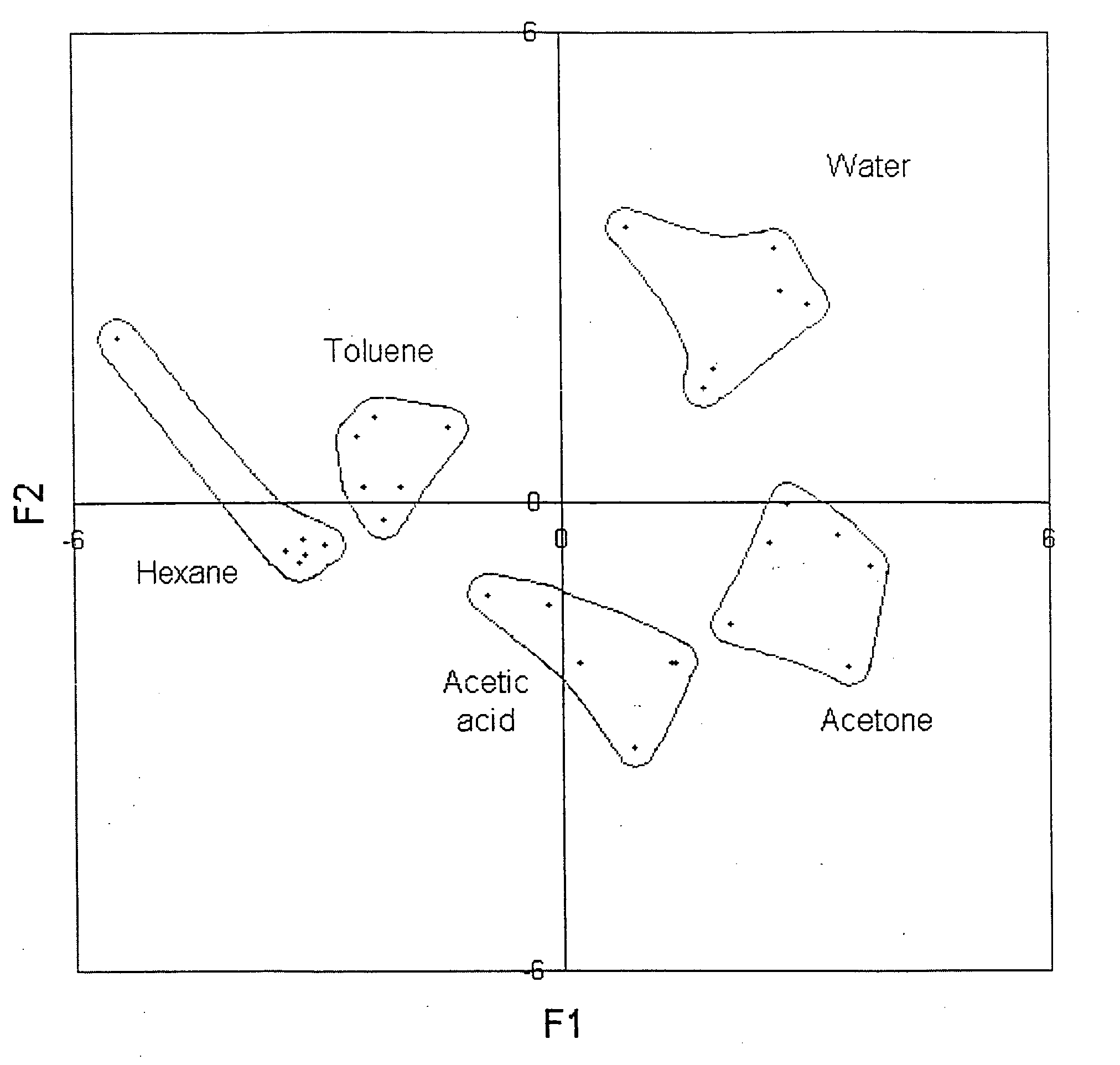
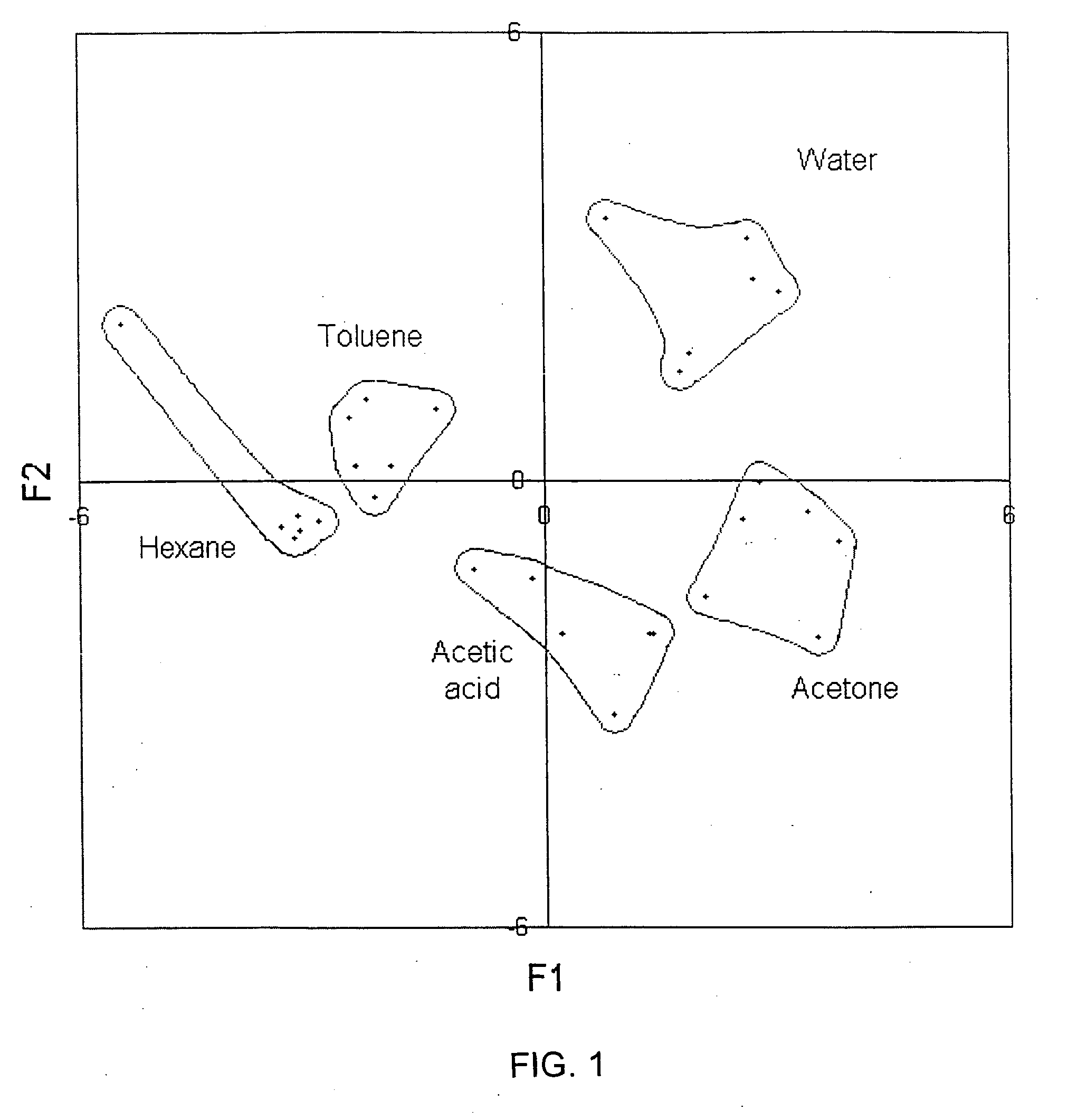
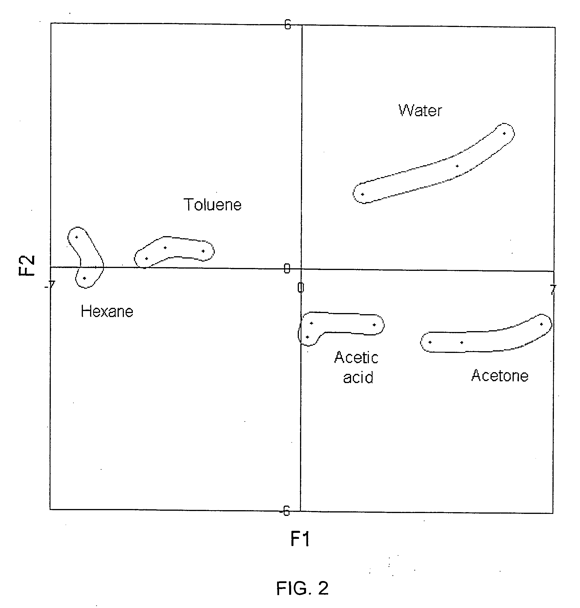
[0163]A pair of electrodes were constructed with gold wires. The electrodes were 12 mm in length and had a gap approximately 1 mm. The electrodes through standard coaxial electrical cables were connected to an AC analyzing device, such as an “Agilent 4294A” impedance analyzer (Agilent, Palo Alto, Calif. USA). Calibration of electrodes was proceeded prior to sample measurement. A frequency sweeping method was used in impedance measurement, where resistance and reactance or impedance and phase angle were simultaneously obtained at each of various swept frequencies. The first experiment was conducted applying frequencies swept from 10 KHz to 500 KHz, and the second experiment used...


PUM

PropertyMeasurementUnit
electrical frequenciesaaaaaaaaaa
electrical propertiesaaaaaaaaaa
impedanceaaaaaaaaaa

Abstract

A sensor instrument system for detecting and identifying analytes in fluids of a region comprising a local sensor instrument and remote central station. The instrument is comprised of a core technology employing a single sensor having two electrodes operated by an electrical frequency sweeping to generate two sets of patterned electrical information from a single measurement, a data transmission module and a GPS receiver module. The central station connects to a network means connected to a plurality of local receiving sites equipped with including the respective transceivers, so that the local analyte electrical information and geographic position information transmitted by the instrument can be wirelessly and remotely received and processed by the central station. The core technology is further comprised of a reference sensor for eliminating background influence, a temperature programming to control adsorption and desorption of analytes, and usage of all kinds of adsorbent materials having chemical selectivity including the hydrogen selectivity to enhance detection and identification of analytes in fluids.

Description

[0001]This application is a continuation-in-part of application Ser. No. 10 / 238,794 filed on Sep. 09, 2002, which has been allowed.BACKGROUND OF THE INVENTION [0002]1. Field of the Invention[0003]The present invention relates generally to the field of sensor instruments, and more particularly relates to a sensor instrument system including methods for detecting analytes in fluids.[0004]2. Description of the Prior Art[0005]Sensor instruments are widely used in the technology of detecting analytes present in fluids. The following references are pertinent to this field of art:[0006]1. U.S. Pat. No. 4,887,455 issued on Dec. 19, 1989 to Payne et al. for “Gas Sensor” (hereafter “the Payne '455 Patent”);[0007]2. U.S. Pat. No. 5,571,401 issued on Nov. 5, 1996 to Lewis et al. for “Sensor Arrays for Detecting Analytes in Fluids” (hereafter “the '401 Lewis Patent”);[0008]3. U.S. Pat. No. 6,319,724 issued on Nov. 20, 2001 to Lewis et al. for “Trace Level Detection of Analytes Using Artificial O...

Claims


Application Information

Patent Timeline
Patent Type & Authority Applications(United States)
IPC IPC(8): H04Q9/00
CPCG01N33/0034G01N35/00732G01N2035/00831B82Y15/00G01N27/3271Y10T436/25375G01N33/54373G01N33/5438G01N27/126G01N33/0075Y10T436/11G01N27/414
Inventor SUN, YIZHONG
Owner SUN YIZHONG
Why Eureka
Try Eureka