Fuel cell system

a fuel cell and system technology, applied in the field of fuel cell systems, can solve the problems of large overall size of the fuel cell system, difficult to maintain the temperature of the exhaust combustion gas, and easy corrosion of the separators, so as to achieve suitably prevent the heat radiation from the fuel cell stack and easily start the suitable operation of the fuel cell stack

Active Publication Date: 2009-10-22
HONDA MOTOR CO LTD
View PDF5 Cites 17 Cited by
  • Summary
  • Abstract
  • Description
  • Claims
  • Application Information

AI Technical Summary

Benefits of technology

[0008]The present invention solves the above problems, and an object of the present invention is to provide a fuel cell system having simple structure in which durability of the combustor is improved effectively, and heat efficiency is improved suitably.
[0011]According to the present invention, the combustion gas produced in the combustor flows through the combustion gas path formed in the space between the inner wall and the outer wall accommodating the fuel cell stack. Then, the combustion gas is supplied from the combustion gas path to the heat exchanger. In the structure, the fuel cell stack is heated from the outside by the hot combustion gas, and heated from the inside by the air which has been used in the heat exchange with the combustion gas at the heat exchanger. Thus, heat radiation from the fuel cell stack is suitably prevented. The fuel cell stack is heated uniformly and rapidly. Accordingly, it is possible to easily start suitable operation of the fuel cell stack.

Problems solved by technology

Therefore, the separators tend to be corroded easily by the hot combustion gas, and carbon in the combustion gas adheres to the separators or the membrane electrode assembly.
However, in the conventional technique, since the two combustors, i.e., the exhaust gas combustor 4 and the start up combustor 6 are provided in the fuel cell system, the overall size of the fuel cell system is large.
Further, at the time of starting operation of the fuel cell system, because the temperature of the exhaust gas discharged from the fuel cell fluctuates, it is extremely difficult to maintain the temperature of the exhaust combustion gas discharged from the exhaust gas combustor 4 in a certain range of the temperature.

Method used


Image

  • Fuel cell system
  • Fuel cell system
  • Fuel cell system

Examples


Embodiment Construction

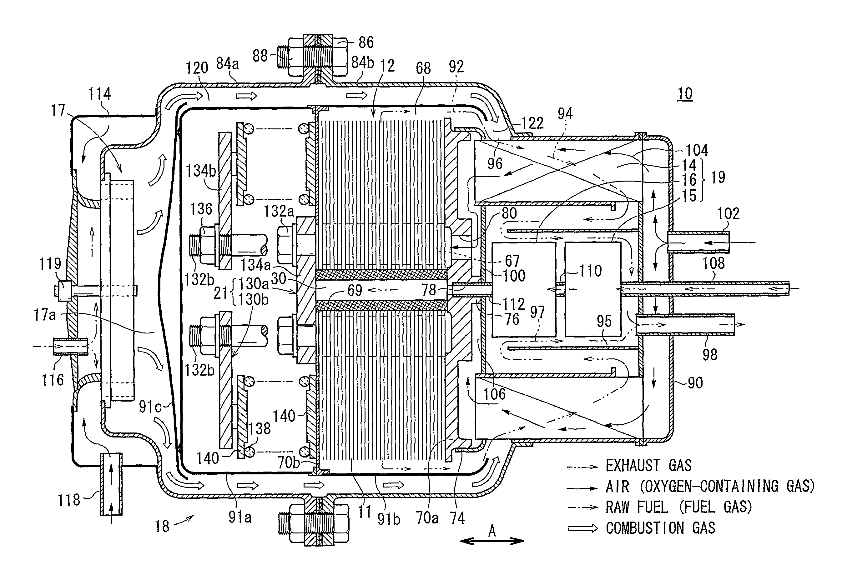
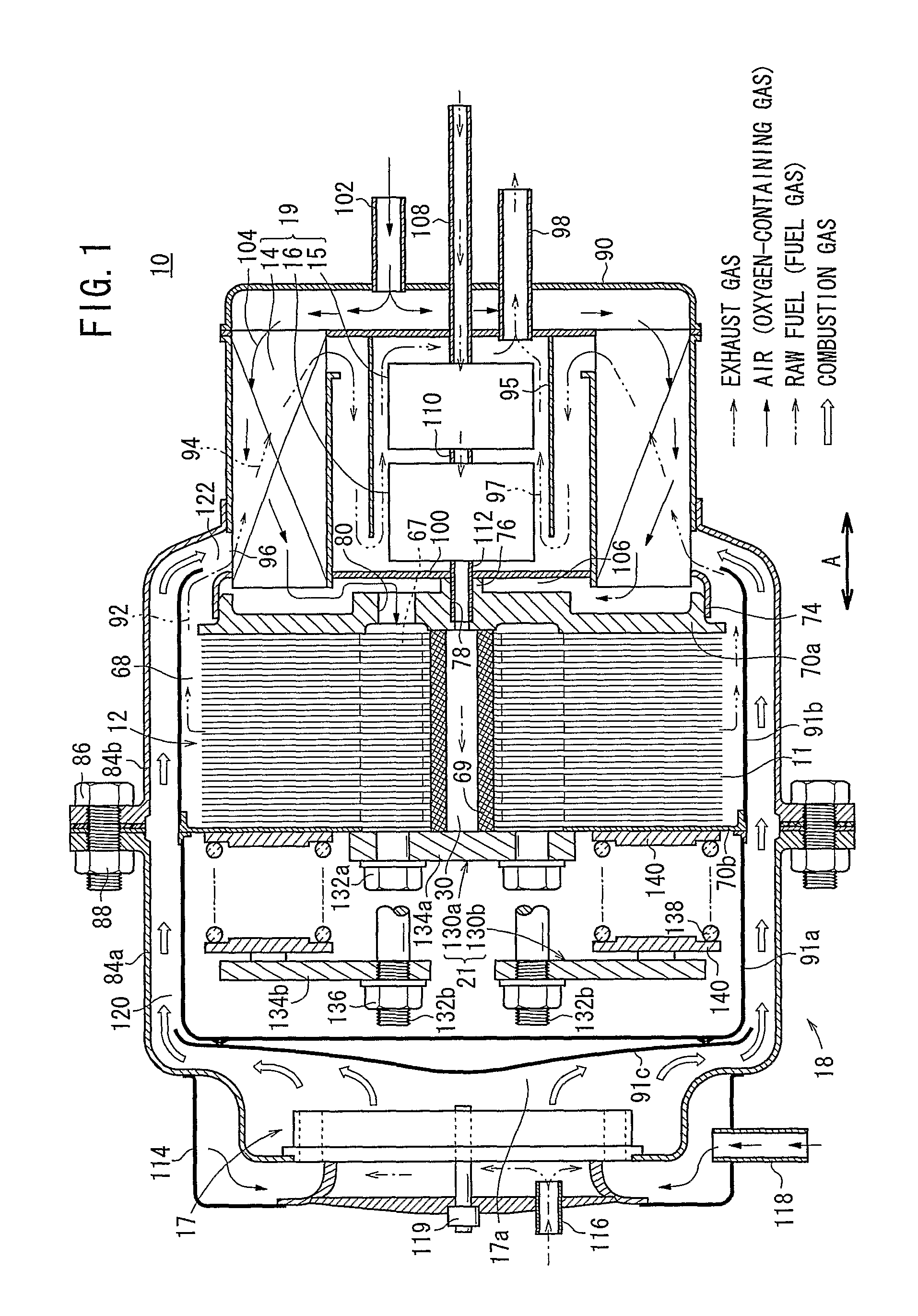
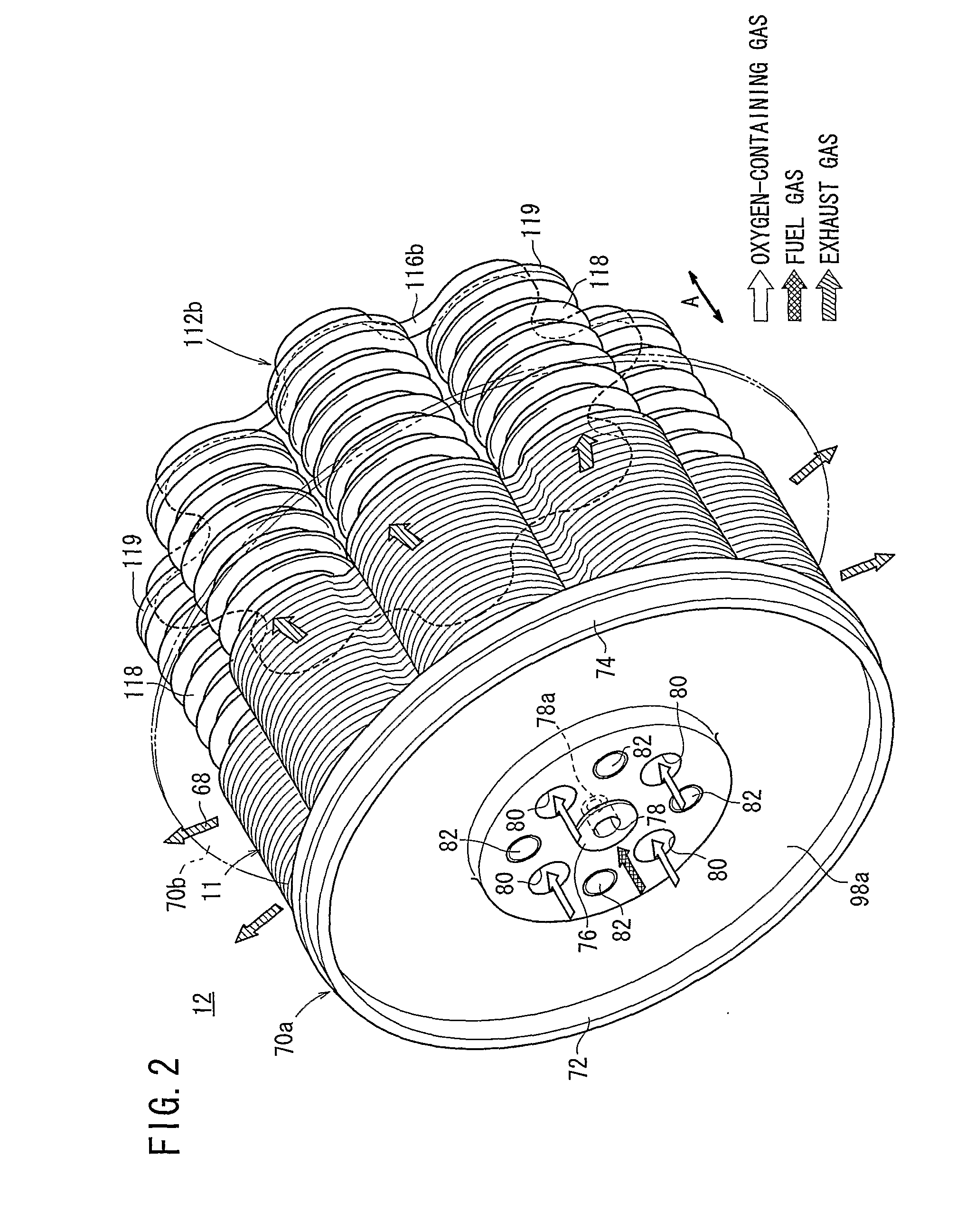
[0019]FIG. 1 is a partial cross sectional view showing a fuel cell system 10 according to an embodiment of the present invention. FIG. 2 is a perspective view schematically showing a fuel cell stack 12 formed by stacking a plurality of fuel cells 11 of the fuel cell system 10 in a direction indicated by an arrow A.

[0020]The fuel cell system 10 is used in various applications, including stationary and mobile applications. For example, the fuel cell system 10 is mounted on a vehicle. As shown in FIG. 1, the fuel cell system 10 includes a fuel cell stack 12, a heat exchanger 14, an evaporator 15, a reformer (or preliminary reformer) 16, a combustor 17, and a casing 18. The heat exchanger 14 heats an oxygen-containing gas before it is supplied to the fuel cell stack 12. The evaporator 15 evaporates water. The reformer 16 uses water vapor (steam) and a raw fuel (e.g., city gas) chiefly containing hydrocarbon for steam reforming of the raw fuel. The combustor 17 burns the raw fuel to prod...


PUM

PropertyMeasurementUnit
operating temperatureaaaaaaaaaa
ion-conductiveaaaaaaaaaa
temperatureaaaaaaaaaa

Abstract

A fuel cell system includes a fuel cell stack, a heat exchanger, a reformer, and a combustor. A combustion gas path for supplying the combustion gas produced in the combustor to the heat exchanger as the heat medium is provided. The combustion gas path is provided between a space of dual walls comprising a first inner plate and a second inner plate and a first case unit and a second case unit accommodating a load applying mechanism and the fuel cell stack.

Description

TECHNICAL FIELD[0001]The present invention relates to a fuel cell system including a fuel cell stack formed by stacking a plurality of fuel cells. Each of the fuel cells is formed by stacking an electrolyte electrode assembly and a separator. The electrolyte electrode assembly includes an anode, a cathode, and an electrolyte interposed between the anode and the cathode.BACKGROUND ART[0002]Typically, a solid oxide fuel cell (SOFC) employs an electrolyte of ion-conductive solid oxide such as stabilized zirconia. The electrolyte is interposed between an anode and a cathode to form an electrolyte electrode assembly (membrane electrode assembly). The electrolyte electrode assembly is interposed between separators (bipolar plates). In use, generally, predetermined numbers of the electrolyte electrode assemblies and the separators are stacked together to form a fuel cell stack.[0003]In the fuel cell stack, the operating temperature of the fuel cell is high, about 800° C. Therefore, at the ...

Claims


Application Information

Patent Timeline
Patent Type & Authority Applications(United States)
IPC IPC(8): H01M8/18
CPCH01M8/04022H01M8/04223H01M8/0612H01M8/0625Y02E60/50H01M8/247H01M8/2475H01M8/248H01M8/12H01M8/2483H01M8/2428H01M8/04225H01M8/2432H01M8/04302
Inventor HOMMA, HIROKI
Owner HONDA MOTOR CO LTD
Why Eureka
Try Eureka