
Resin Composition Excellent in Flame Retardance

a technology of composition and flame retardancy, applied in the field of resin composition, can solve the problems of increased dimensional change during water absorption, defective appearance of molded pieces, and insufficient flowability, and achieve the effects of reducing the generation of deposits, and reducing the generation of gas

Inactive Publication Date: 2009-11-05
ASAHI KASEI CHEM CORP
View PDF12 Cites 30 Cited by
  • Summary
  • Abstract
  • Description
  • Claims
  • Application Information

AI Technical Summary

Benefits of technology

[0010]An object of the present invention is to provide a resin composition excellent in flame retardancy, impact resistance and moldability into a thin-walled component and capable of giving a molded product excellent in surface appearance. Specifically, the object of the present invention is to provide a resin composition which is excellent in flowability and further capable of significantly suppressing gas generation during processing and substantially inhibiting the generation of deposits on a mold (hereinafter sometimes referred to as mold deposits) during injection molding.Means for Solving the Problems
[0016]The use of the present invention provides a resin composition which is excellent in flame retardancy, impact resistance, and moldability into thin-walled components and capable of significantly suppressing gas generation during the molding process and substantially inhibiting the generation of deposits on a mold (mold deposits) during injection molding. As a result, a molded product excellent in surface appearance can be provided.

Problems solved by technology

Among others, polyamide 6,6 has conventionally been used in a relay box installed in an automobile engine room; however, it has had a problem of suffering an increased dimensional change during water absorption.
However, SMT-applicable components typified by a relay box, a connector and the like of recent years have each been made in a more complex, smaller and more thin-walled shape, posing problems that deposits called mold deposits adhere to the mold during injection molding, that a defective appearance of a molded piece (hereinafter sometimes referred to as silver streaks) occurs due to gas generated during the molding, and further that insufficient flowability does not enable the successful molding of a thin-walled component.
The techniques proposed above cannot solve these problems; it has been essential to solve them.

Method used


Image

  • Resin Composition Excellent in Flame Retardance
  • Resin Composition Excellent in Flame Retardance
  • Resin Composition Excellent in Flame Retardance

Examples


examples

[0177]The present invention will now be described in further detail by way of Examples and Comparative Examples. However, the invention is not intended to be limited to these Examples.

[0178]Note that the raw materials and measurement methods used in Examples and Comparative Examples are described below.

Raw Materials

[0179](A) Polyamide

[0180](A-1) Polyamide 9T (Hereinafter Abbreviated as PA9T-a)

[0181]With reference to the method described in the Examples of JP-A-2000-204239, 3,256.2 g (19.6 mol) of terephthalic acid, 2,690.9 g (17.0 mol) of 1,9-nonanediamine, 474.9 g (3.0 mol) of 2-methyl-1,8-octanediamine, 97.7 g (0.8 mol) of benzoic acid, 6.5 g (0.1% by weight based on the total of the preceding four polyamide raw materials) of sodium hypophosphite monohydrate, and 6 litters of distilled water were placed in an autoclave having an inner volume of 20 litters, whose inside was then purged with nitrogen. The autoclave was stirred at 100° C. for 30 minutes, followed by raising the inter...

examples 1 to 13 and 16 to 18

and Comparative Examples 2 to 4

[0257]A twin screw extruder having one supply port on the upstream side and two supply ports on the downstream side (one port at the position of 0.4 and one port at the position of 0.8 when the overall length of the extruder cylinder was set to 1.0) (ZSK-26MC manufactured by Coperion Holding GmbH (Germany)) was provided. The cylinder temperature was set to 320° C. from the supply port on the upstream side (hereinafter referred to as the upstream supply port) to the supply port at the position of L=0.4 (hereinafter referred to as the central supply port) and, downstream to the central supply port, 310° C. when polyamide 9T was used and 280° C. when polyamide 66 was used.

[0258]According to the compositions described in Tables 1 to 4, raw materials for each thereof were supplied and melt-kneaded to provide pellets. To control the moisture content of the pellets, after extrusion, the pellets were dried in a dehumidification drier set at 80° C. and then pla...

example 14

[0264]According to the composition described in Table 3, raw materials therefor were melt-kneaded under the same conditions as in Example 1 to provide pellets. The resultant pellet was attempted to be molded, but a molding tool could not completely be filled with the resin under the condition of a cylinder temperature of 320° C. Accordingly, when the pellets was again attempted to be molded by raising the cylinder temperature to 330° C., the filling was completed. This obtained molded piece was subjected to the above evaluations.


PUM

PropertyMeasurementUnit
Fractionaaaaaaaaaa
Percent by massaaaaaaaaaa

Abstract

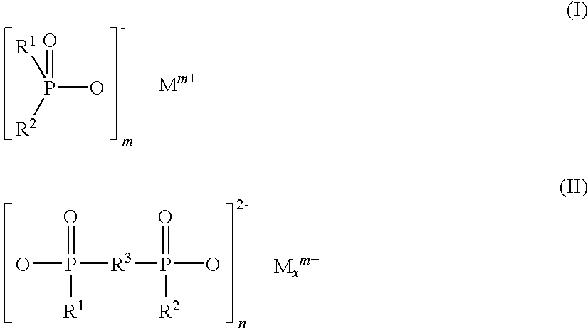
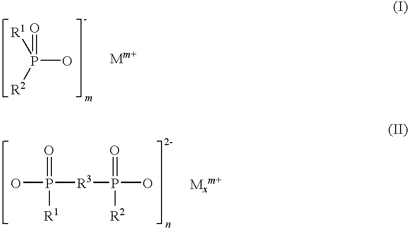
The present invention relates to a resin composition containing (A) a polyamide having a viscosity number (as measured in the 96% sulfuric acid according to ISO 307 (1997)) of from 50 ml / g to 250 ml / g; (B) a polyphenylene ether; and (C) a phosphinate represented by a particular formula. The resin composition according to the present invention is excellent in flame retardancy, impact resistance and thin-wall moldability and can significantly suppress gas generation during the molding process and substantially inhibit the generation of deposits on a mold during injection molding. As a result, a molded product thereof excellent in surface appearance can be provided.

Description

TECHNICAL FIELD[0001]The present invention relates to a resin composition which is excellent in flame retardancy, impact resistance, and moldability into thin-walled components such as a connector in the electric and electronic field, and which has excellent characteristics enabling the significant suppression of gas generation during processing and the substantial inhibition of generation of deposits on a mold (mold deposits) during injection molding. The resin composition can be suitably used in components including electrical and electronic components such as a connector, a breaker, and a magnet switch, electrical components in the automobile field, typified by a relay box, and components applicable with a surface-mount technology (hereinafter sometimes referred to as SMT), requiring lead-free solder resistance.BACKGROUND ART[0002]Polyamides have previously been used in many fields including automobile components, machine components, and electrical and electronic components becau...

Claims


Application Information

Patent Timeline
IPC IPC(8): C08K5/5313
CPCC08K5/5313C08L71/12C08L77/00C08L2666/20C08L2666/22
Inventor FURUKAWA, HIROAKIMIYOSHI, TAKAAKISHIKANO, YASUKAZUDOKI, MAKOTO
Owner ASAHI KASEI CHEM CORP
Learn More