
Optical cavity-enhanced photo acoustic trace gas detector with variable light intensity modulator

a technology of variable light intensity modulator and optical cavity, which is applied in the field of photo acoustic trace gas detector, can solve the problems of increasing thermal energy, no feedback signal, and local rise of temperature and pressure inside the acoustic cell, and achieves high sensitivity of the crystal oscillator, high accuracy, and simplified construction of the detector

Inactive Publication Date: 2009-11-26
KONINKLIJKE PHILIPS ELECTRONICS NV
View PDF11 Cites 33 Cited by
  • Summary
  • Abstract
  • Description
  • Claims
  • Application Information

AI Technical Summary

Benefits of technology

[0008]Because the light intensity does not drop to zero, an uninterrupted feedback signal is provided. In this way a fast and more stable feedback lock loop can be implemented and portable application of the detector is made possible.
[0010]The means for adjusting allow the user, or an automated system, to adjust the strength of the feedback signal for the feedback loop with respect to the photo-acoustic modulated signal. When a strong feedback signal is required, more light intensity is used for the feedback loop. In more stable conditions more light intensity may be used for providing the pressure variations in the gas flow cell and less for the feedback signal, resulting in an improved accuracy of the trace gas detector. The means for adjusting may, for example, comprise filters with adjustable transparency.
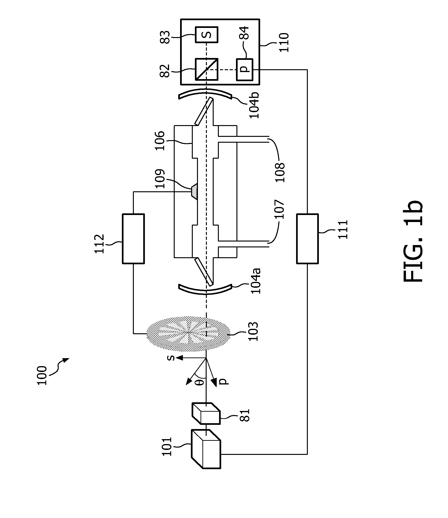
[0012]In this embodiment, the light with the second polarization is continuously available for use as a feedback signal, while the light with the first polarization is modulated for causing the desired pressure variations in the gas flow cell. It is an advantage of this embodiment that the feedback signal is relatively stable and is not influenced by the light intensity transitions needed for providing the light pulses.
[0014]By rotating the polarization of the laser light, the ratio of the intensities of the light with the first and the second polarization can be varied. This allows the user, or an automated system, to adjust the strength of the feedback signal for the feedback loop with respect to the photo-acoustic modulated signal.
[0015]In a preferred embodiment the transducer is a crystal oscillator. A crystal oscillator is much more sensitive than the microphone used in the above mentioned prior art system. Consequently, a more sensitive photo acoustic trace gas detector is obtained. As an additional advantage, the high sensitivity of the crystal oscillator makes the use of an acoustic cell not essential and thereby simplifies the construction of the detector.
[0016]In a further embodiment the crystal oscillator is a quartz tuning fork. Quartz tuning forks have a high accuracy. Furthermore, quartz tuning forks are not very expensive because they are used on large scale, for example, for the manufacturing of digital watches.

Problems solved by technology

This excitation leads to an increase of the thermal energy, resulting in a local rise of the temperature and the pressure inside the acoustic cell.
It has the drawback that no feedback signal is present when the chopper blocks the laser beam and the transmitted intensity is zero.
Therefore, no cavity feedback can be given to the laser during these periods and the cavity can become unlocked when it is disturbed.
The result is a loss of optical power and a concomitant decrease of photo acoustic signal strength.
Consequently, the cavity locking mechanism is slow.
Currently, exhaled NO levels at ppb concentrations can be only measured using expensive and bulky equipment based on chemiluminescence or optical absorption spectroscopy.
It is the challenge for these hand-held gas-analyzing devices to combine sufficient high sensitivity (ppb level) with a high robustness.
Current photo acoustic trace gas detectors have the disadvantage that small form factor lasers (i.e. diode lasers) do not have sufficient laser power to reach the sensitivity required for trace gas detection.
The use of an optical power enhancement cavity as described by Rossi et al. could increase the optical power, but that would lead to a slow feedback.
Consequently, the cavity locking mechanism becomes very slow, which results in a system that is not robust enough for portable applications.

Method used


Image

  • Optical cavity-enhanced photo acoustic trace gas detector with variable light intensity modulator
  • Optical cavity-enhanced photo acoustic trace gas detector with variable light intensity modulator
  • Optical cavity-enhanced photo acoustic trace gas detector with variable light intensity modulator

Examples


Embodiment Construction

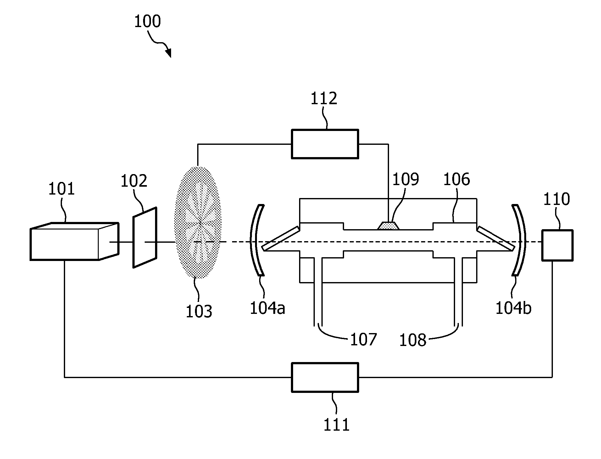
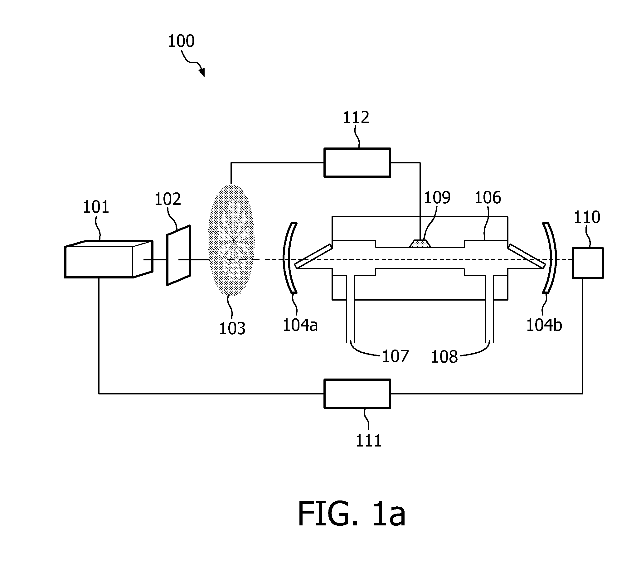
[0028]FIG. 1a shows a typical photo acoustic trace gas detector 100 according to the invention. A light source 101 provides a continuous wave laser beam and is modulated into a series of light pulses at a certain ‘chopping’ frequency by, e.g., a chopper 103, shutter or acousto-optic modulator. Alternatively, the light source 101 itself may provide the light pulses at a fixed frequency. The light pulses are sent into an optical cavity, which is defined by two semi-transparent mirrors 104a and 104b. An optical isolator 102 is optionally placed between the light source 101 and the input mirror 104a to reduce the reflectance of light from the cavity mirror 104a into the light source 101. The light pulses enter the optical cavity through input mirror 104a and are reflected many times between the two cavity mirrors 104a and 104b. If the distance between the two mirrors 104a and 104b is in resonance with the wavelength of the laser, standing waves occur and the light intensity is amplified...


PUM

PropertyMeasurementUnit
chopping frequencyaaaaaaaaaa
concentrationaaaaaaaaaa
light intensityaaaaaaaaaa

Abstract

A photo acoustic trace gas detector (100) is provided for detecting a concentration of a trace gas in a gas mixture. The detector (100) comprises a light source (101) for producing a light beam and a light modulator (103) for modulating the light beam into a series of light pulses for generating sound waves in the gas mixture. The light modulator (103) is arranged for modulating the light beam between a non-zero lower intensity level and a higher intensity level. An amplitude of the sound waves being a measure of the concentration. An optical cavity (104a, 104b) contains the gas mixture and amplifies a light intensity of the light pulses. A transducer (109) for converts the sound waves into electrical signals. A feed back loop (110, 111) with a photo detector (110) for measuring the light intensity of the light pulses regulates the amplification of the light intensity in the optical cavity (104a, 104b).

Description

TECHNICAL FIELD OF THE INVENTION[0001]The invention relates to a photo acoustic trace gas detector for detecting a concentration of a trace gas in a gas mixture, the photo acoustic trace gas detector comprising a light source for producing a light beam, a light modulator for modulating the light beam into a series of light pulses for generating sound waves in the gas mixture, an amplitude of the sound waves being a measure of the concentration, an optical cavity for containing the gas mixture and for amplification of a light intensity of the light pulses, a transducer for converting the sound waves into electrical signals, and a feedback loop for regulating the amplification of the light intensity of the light pulses in the optical cavity, the feedback loop comprising a photo detector for measuring the light intensity of the light pulses.BACKGROUND OF THE INVENTION[0002]Such a detector is known from the article “Optical enhancement of diode laser-photo acoustic trace gas detection b...

Claims


Application Information

Patent Timeline
Patent Type & Authority Applications(United States)
IPC IPC(8): G01N21/17
CPCA61B5/0095A61B5/083G01N2291/0427G01N29/2425G01N2021/1704G01N21/1702
Inventor KALKMAN, JEROENVAN HERPEN, MAARTEN MARINUS JOHANNES WILHELMUS
Owner KONINKLIJKE PHILIPS ELECTRONICS NV
Learn More