Electrochemical reactor units and modules and systems composed of them

a technology of electrochemical reactors and modules, applied in the direction of fuel cell details, electrochemical generators, final product manufacture, etc., can solve the problems of cell failure, large volume change, strain in the cell,

Active Publication Date: 2009-11-26
NAT INST OF ADVANCED IND SCI & TECH
View PDF2 Cites 28 Cited by
  • Summary
  • Abstract
  • Description
  • Claims
  • Application Information

AI Technical Summary

Benefits of technology

[0090](7) The electrochemical reaction system of the present invention can be used to advantage as an elect

Problems solved by technology

However, the anode support-type SOFCs having a high power output that have been reported on up to now are flat, and under conditions of a harsh operating cycle, a problem is that the cell can sometimes fail.
The reason for this is that the nickel-cermet that is commonly used undergoes a large change in volume due to temperature changes or redox atmosphere cycling, and this causes strain in the cell and leads to failure.
Consequently, if

Method used


Image

  • Electrochemical reactor units and modules and systems composed of them
  • Electrochemical reactor units and modules and systems composed of them
  • Electrochemical reactor units and modules and systems composed of them

Examples


working example 1

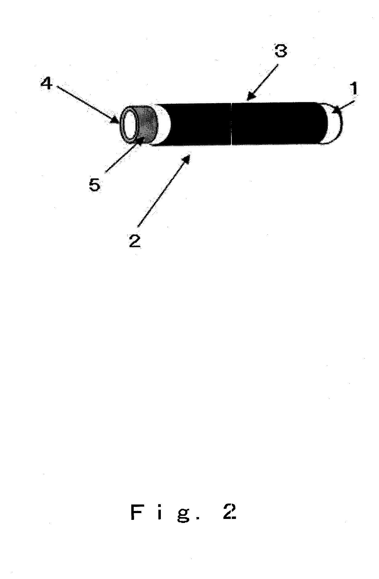
[0108]In this working example, tube-type electrochemical reactor cells (see FIG. 7) were produced by the following procedure. First, nitrocellulose was added as a binder to a powder (made by Anan Kasei) having a composition of NiO (made by Wako) and CeO2-10 mol % Gd2O3 (GDC), this was kneaded with water and put into a clay-like consistency, after which it was extrusion molded to produce a tubular molded article. The diameter and thickness of the tube thus obtained were 1 mm and 0.2 mm, respectively.

[0109]Next, the opening at one end of the tube was sealed with vinyl acetate, after which this tube was immersed in a slurry containing a solid electrolyte with a GDC composition, thereby dip coating a layer that would form an electrolyte layer, and obtaining an electrolyte-attached tube as an anode tube. The other end of the anode tube was left exposed for 3 mm, creating an anode exposed part.

[0110]Next, this tubular molded article was dried and then fired for 2 hours at 1400° C., which ...

working example 2

[0114]The tube-type electrochemical reactor units obtained in Working Example 1 above were connected to a gas introduction pipe. The connected part was sealed with ceramic paste, and hydrogen and air were supplied as fuel gasses to the tube-type electrochemical reactor unit. FIG. 10 shows the results of a power generation performance test of the above-mentioned electrochemical reactor unit at a temperature of 400 to 490° C. It was proven that the tube-type electrochemical reactor unit of the present invention can generate a power output of at least 2.5 W / cc per unit, even at low temperatures of 500° C. or lower.

working example 3

[0115]The air pressure loss with the tube-type electrochemical reactor units obtained in Working Example 1 above was compared with that of a conventional tube-type electrochemical reactor structure produced by a conventional method (see FIG. 7). The gas permeation coefficient of the porous collector body was measured at room temperature and found to be 6.2×10⁻⁴ mL cm cm−2 sec−1 Pa−1. This value was used to find the pressure loss at 550° C. for the shape of the units of the present invention and the shape obtained by the conventional method.

[0116]FIG. 11 is a graph of the gas flow that can permeate with the electrochemical reactor unit, as a function of pressure loss. This graph shows the gas flow that can permeate at a given pressure differential, and with the units of the present invention, it was found that gas can permeate at a high flow rate even at a low pressure differential. This suggests that controlling the air flow will be easy, which tells us that temperature control will...


PUM


Abstract

The present invention is an electrochemical reactor unit in which a plurality of electrochemical reactor cells constituted by a tube are housed in a porous material body having a heat releasing function and a current collecting function, these are electrically connected in series, and a fuel manifold is mounted to the connected electrochemical reactor cells; an electrochemical reactor module that comprises a plurality of the units which are arranged in fuel supply holes, and a structure supplying air directly to the entire electrochemical reactor module; and an electrochemical reaction system in which such an electrochemical reactor module is utilized.

Description

BACKGROUND OF THE INVENTION[0001]1. Field of the Invention[0002]The present invention relates to an electrochemical reactor unit composed of an electrochemical reactor cell stack, and to an electrochemical reaction system, such as a solid oxide fuel cell, made up of these electrochemical reactor cell stacks, and more particularly relates to an electrochemical reactor unit, electrochemical reactor module, and electrochemical reaction system that make use of tube-type electrochemical reactor cells and that afford a marked increase in the output per unit of volume.[0003]The present invention provides a novel technique and a novel product relating to an electrochemical reactor unit and reactor module that can be used to advantage as an electrochemical reaction system such as an environmental purification apparatus or a clean energy source, and to an electrochemical reaction system in which such a reactor module is utilized.[0004]2. Description of the Related Art[0005]A solid oxide fuel ...

Claims


Application Information

Patent Timeline
IPC IPC(8): H01M8/10
CPCH01M8/0206H01M8/0215H01M8/0247H01M8/0276H01M8/04074Y02E60/525H01M8/124H01M8/243H01M8/2475H01M8/249Y02E60/521H01M8/04089Y02E60/50Y02P70/50H01M8/2457H01M8/2484
Inventor SUZUKI, TOSHIOYAMAGUCHI, TOSHIAKIFUJISHIRO, YOSHINOBUAWANO, MASANOBU
Owner NAT INST OF ADVANCED IND SCI & TECH
Why Eureka
Try Eureka