
Continuous Process for the Production of Nanostructures Including Nanotubes

a nanotube and continuous process technology, applied in the direction of gas-gas reaction process, liquid-gas reaction of thin-film type, physical/chemical process catalyst, etc., can solve the problems of cnt agglomeration, poor alignment of cnt axes, and dispersion of cnts in secondary materials

Active Publication Date: 2009-12-17
MASSACHUSETTS INST OF TECH
View PDF21 Cites 137 Cited by
  • Summary
  • Abstract
  • Description
  • Claims
  • Application Information

AI Technical Summary

Benefits of technology

[0012]The present invention also relates to composite articles comprising a first material layer, and a second material layer integrally connected to the first material layer, forming an interface of the material layers, the interface comprising a set of nanostructures, wherein the long axes of the nanostructures are substantially aligned and non-parallel to interface of the material layers and wherein the nanostructures have an average diameter of 100 nm or less.

Problems solved by technology

While the use of CNTs in composite materials has been studied, existing CNT processing techniques often display several drawbacks.
For example, the syntheses of CNTs often result in structures having large diameter and insufficient length, which often results in poor alignment of the CNT axes.
Also, dispersion of the CNTs in secondary materials, which typically requires uniform wetting of the CNTs by the secondary materials, is often hindered by CNT agglomeration.
Last, alignment of CNTs in the secondary materials may be difficult to achieve in general, particularly when alignment of nanotubes is desired in a system comprising large (e.g., orders of micron diameter) advanced fibers, a secondary material (matrix), and well-aligned CNTs in the secondary material.

Method used


Image

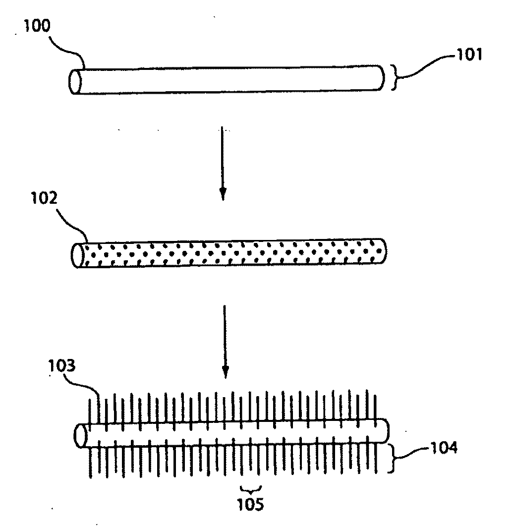
  • Continuous Process for the Production of Nanostructures Including Nanotubes
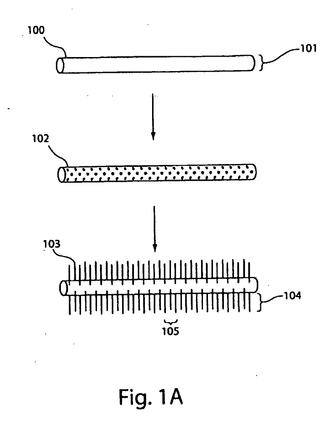
  • Continuous Process for the Production of Nanostructures Including Nanotubes
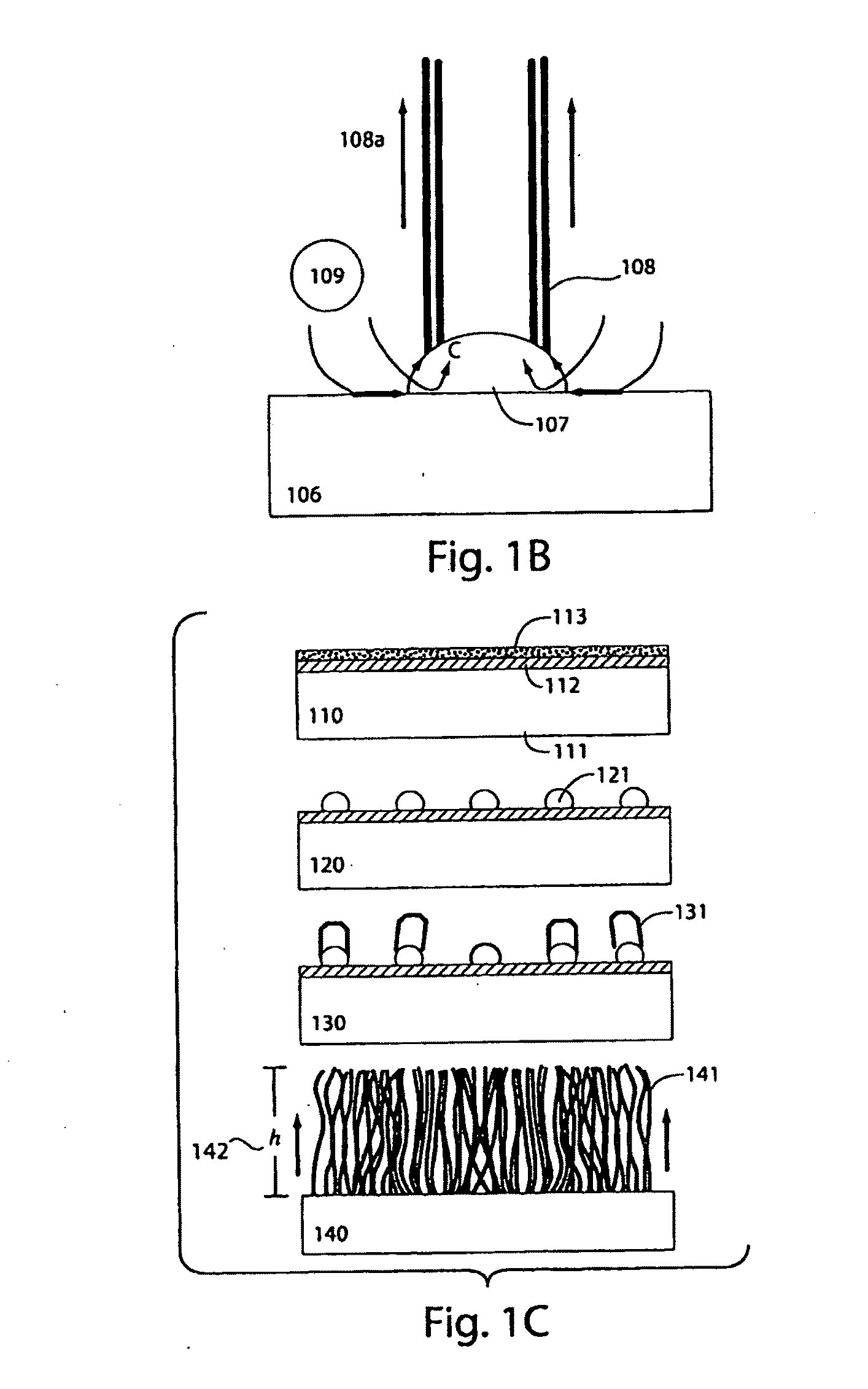
  • Continuous Process for the Production of Nanostructures Including Nanotubes

Examples


example 1

[0155]The following example describes an exemplary process for growing layers of aligned carbon nanotubes on a substrate. A patterned catalyst film of 1 / 10 nm Fe / Al2O3 was deposited on a plain (100) 6″ silicon wafer (p-type, 1-10 Ω-cm, Silicon Quest International, which was cleaned using a standard “piranha” (3:1 H2SO4:H202) solution) by e-beam evaporation in a single pump-down cycle using a Temescal VES-2550 with a FDC-8000 Film Deposition Controller. The catalyst pattern was fabricated by lift-off of a 1 μm layer of image-reversal photoresist (AZ-5214E), which was patterned by photolithography. The catalyst was deposited over the entire wafer surface, and the areas of catalyst that were deposited on the photoresist were removed by soaking in acetone for 5 minutes, with mild sonication. The film thickness of the catalyst was measured during deposition using a quartz crystal monitor and was later confirmed by Rutherford backscattering spectrometry (RBS).

[0156]CNT growth was performe...

example 2

[0161]The following examples describes the production of ceramic fibers containing carbon nanotubes on the surface of the fibers. Fiber strands were cut from a commercially-available (McMaster-Carr) aluminum oxide (Al2O3) fiber cloth and soaked for five minutes in a 10 mM solution of Fe(NO3)3.9H2O in isopropanol (prepared by stirring and sonication). The fiber strands were then allowed to dry in air. FIG. 15 shows SEM images of the Al2O3 fibers loaded with the iron catalyst material on a (a) 100 micron and (b) 20 micron scale. The Al2O3 fibers were about 20 μm in diameter, each strand comprising several hundred fibers. Carbon nanotube growth was performed using a single-zone atmospheric pressure quartz tube furnace (Lindberg) having an inside diameter of 22 mm and a 30 cm long heating zone. Flows of Ar (99.999%, Airgas), C2H4 (99.5%, Airgas), and H2 (99.999%, BOC) were measured using manual needle-valve rotameters. The furnace temperature was held at 750° C., with 100 / 500 / 200 sccm C...

example 3

[0165]The following example describes the production of composite thin films containing vertically-aligned carbon nanotubes. A pattern of rectangular “pillars” containing carbon nanotubes was grown on a silicon wafer, according to the process described in Example 1. The carbon nanotubes were vertically-aligned and substantially perpendicular to the substrate, and were held together in the form of pillars by surface forces. By adjusting the either the concentration of C2H4 in the reaction chamber or the reaction temperature, it was possible to control the growth rate and height of the carbon nanotube pillars. In this example, the carbon nanotube height was measured to be 100 μm.

[0166]The carbon nanotubes on the silicon wafer were then combined with a second substrate to form a composite thin film. A fast-curing (e.g., 20 minute) room-temperature conductive epoxy was deposited on a glass substrate (e.g., the “second” substrate) in the form of a thin film having a thickness approximate...


PUM

PropertyMeasurementUnit
temperatureaaaaaaaaaa
diameteraaaaaaaaaa
volume fractionaaaaaaaaaa

Abstract

The present invention provides methods for uniform growth of nanostructures such as nanotubes (e.g., carbon nanotubes) on the surface of a substrate, wherein the long axes of the nanostructures may be substantially aligned. The nanostructures may be further processed for use in various applications, such as composite materials. For example, a set of aligned nanostructures may be formed and transferred, either in bulk or to another surface, to another material to enhance the properties of the material. In some cases, the nanostructures may enhance the mechanical properties of a material, for example, providing mechanical reinforcement at an interface between two materials or plies. In some cases, the nanostructures may enhance thermal and / or electronic properties of a material. The present invention also provides systems and methods for growth of nanostructures, including batch processes and continuous processes.

Description

STATEMENT REGARDING FEDERALLY SPONSORED RESEARCH OR DEVELOPMENT[0001]This invention was made with the support under the following government contract: DMI-0521985 awarded by the National Science Foundation. The government has certain rights in the invention.FIELD OF THE INVENTION[0002]The present invention generally relates to the synthesis and processing of nanostructures, composite materials comprising nanostructures, and related systems and methods.BACKGROUND OF THE INVENTION[0003]Composites are heterogeneous structures comprising two or more components, the combination taking advantage of the individual properties of each component as well as synergistic effects if relevant. Advanced composites refer to a class of materials in which engineered (e.g., man-made) fibers are embedded in a matrix, typically with the fibers being aligned or even woven such that a material with directional (anisotropic) properties is formed. A common example of an advanced composite is graphite-epoxy (...

Claims


Application Information

Patent Timeline
Patent Type & Authority Applications(United States)
IPC IPC(8): C01B31/02B05D3/10
CPCB82B1/00B82Y30/00B82Y40/00C01B31/0233D06M23/08C01B31/0293D01F9/127D01F9/133D06M11/74C01B31/024Y02P20/584Y02P20/582C01B32/16C01B32/162C01B32/164C01B32/18Y10S977/742Y10S977/843C01B32/158C08K3/041B01J21/04B01J23/745C01B2202/08
Inventor HART, ANASTASIOS JOHNWARDLE, BRIAN L.GARCIA, ENRIQUE J.SLOCUM, ALEXANDER HENRY
Owner MASSACHUSETTS INST OF TECH
Learn More