Secondary battery pack having excellent production process property and structural stability

a technology of production process and structural stability, applied in the direction of batteries, sustainable manufacturing/processing, cell components, etc., can solve the problems of high degree of technical skill in welding or soldering process, high degree of safety of lithium secondary battery, and high degree of heat or explosion of lithium secondary battery. to achieve the effect of maximizing the

Active Publication Date: 2009-12-24
LG ENERGY SOLUTION LTD
View PDF3 Cites 15 Cited by
  • Summary
  • Abstract
  • Description
  • Claims
  • Application Information

AI Technical Summary

Benefits of technology

[0013]As a result of a variety of extensive and intensive studies and experiments to solve the problems as described above, the inventors of the present invention have found that, when an insulative mounting member is coupled to the top of a battery cell, through a specific coupling structure, to construct a secondary battery pack, the assembly process of the secondary battery pack is greatly simplified, the safety of the battery cell during the manufacture of the battery cell is secured, and, at the same time, it is possible to maintain an improved coupling strength.
[0017]In this structure, the at least one coupling member is not exposed to the outside. Consequently, a possibility of a short circuit occurring is minimized while the pleasing aesthetic appearance of the battery pack is not deteriorated. Furthermore, the number of members mounted to the top of the battery cell is reduced through the insulative mounting member, with the result that the assembly process is simplified, and therefore, the production efficiency is improved.
[0029]In another embodiment, the at least one coupling member has a thread part formed at the outside thereof. For example, the at least one coupling member may be a screw or a bolt. Preferably, the at least one coupling member is a screw. A female type thread structure corresponding to the at least one coupling member may be formed at the inside of the at least one coupling groove, formed at the top of the battery case. Alternatively, a female type thread structure may be formed at the inside of the at least one coupling groove during the insertion of the at least one coupling member into the at least one coupling groove. Consequently, the formation of the female type thread structure at the inside of the at least one coupling groove is not critical. Consequently, when the thread part, corresponding to the coupling member, is formed at the coupling groove, the engaging force between the coupling member and the coupling groove is further increased, and therefore, a more stable structure is maintained.
[0032]The insulative cap serves to protect the battery cell against external impacts, to complement the mechanical strength of the members mounted to the top of the battery cell, and, at the same time, to maintain the electrical insulation. To this end, the insulative cap may extend downward by a predetermined length sufficient for at least some of the insulative cap to surround the outside of the top of the battery cell while the insulative cap is mounted on the battery cell. In order to maximize this effect, the downward extending portion of the insulative cap may be fixed to the outside of the top of the battery cell by a bonding fashion or a mechanical coupling fashion.
[0033]The secondary battery pack may further include another insulative cap (bottom cap) coupled to the bottom of the battery cell in addition to the insulative cap coupled to the top of the battery cell. Furthermore, the secondary battery pack may further include a sheathing film attached to the outer surface of the battery case of the battery cell. Consequently, it is possible to protect the battery cell against external impacts and to maintain the electrical insulation. Preferably, the sheathing film is attached to the outer surface of the battery case of the battery cell such that the sheathing film surrounds the downward extending portion of the insulative cap.

Problems solved by technology

As a result, the lithium secondary battery may be heated or explode due to the overcharge of the battery, the overcurrent in the battery, or other physical external impacts.
That is, the safety of the lithium secondary battery is very low.
However, the welding or soldering process requires a high degree of technical skill, with the result that skilled persons are needed.
Also, the welding or soldering process requires a large working space.
Furthermore, when physical impacts are applied to the battery cell, electrical shorts may occur, and therefore, the battery cell may catch fire or explode.
In other words, safety-related problems may occur.
However, the above-described technology has a problem in that the welding process is still used to couple the rod-shaped connecting members to the top of the battery cell, and therefore, the manufacturing process is difficult, and the safety of the battery cell is still low.
However, the above-described technologies have a problem in that an additional coupling structure is formed at the top of the battery cell, which is very troublesome.
Especially for the latter case, the protrusion type coupling structure is formed at the top of the battery cell, and, a welding process is used to form the protrusion type coupling structure, whereby the manufacturing process is difficult, and the safety of the battery cell is still low.
However, the above-described technologies have problems in that an additional member is inserted between terminals of the battery cell and the protection circuit board for accomplishing the electrical insulation between the terminals of the battery cell and the protection circuit board, and it is required to provide additional connecting members, such as connection pins, for the electrical connection with the electrode terminals, whereby the assembly process is complicated.
Especially for the latter case, the connecting members may be easily separated from the electrode terminals, with the result that an external short circuit may occur, and the battery pack may become defective during the handling and manufacture of the battery pack.
Such additional provision of the insulative / conductive members complicates the assembly process.
Also, the manufacturing process is very complicated, and the safety of the battery cell is deteriorated, when the welding process is used.
Furthermore, the screws necessary for the coupling are partially exposed to the outside, with the result that a possibility of a short circuit occurring is increased.
In addition, the battery does not exhibit a pleasing aesthetic appearance, which acts as a deterring factor when consumers choose products.

Method used


Image

  • Secondary battery pack having excellent production process property and structural stability
  • Secondary battery pack having excellent production process property and structural stability
  • Secondary battery pack having excellent production process property and structural stability

Examples


example 1

[0082]Slurry, prepared by adding lithium cobalt oxide, PVdf, and a conducting agent in a generally known composition ratio, was coated on an aluminum foil to manufacture cathodes. Slurry, prepared by adding graphite, PVdf, and a conducting agent in a generally known composition ratio, was coated on a copper foil to manufacture anodes.

[0083]Separators, having a size slightly greater than that of the cathodes and the anodes, were disposed respectively between the cathodes and the anodes to manufacture an electrode assembly. The manufactured electrode assembly was mounted in a prismatic aluminum battery container. A battery container cover was mounted to the battery container, an electrolyte was injected into the battery container through an injection port, and the injection port was hermetically sealed, to manufacture a battery cell.

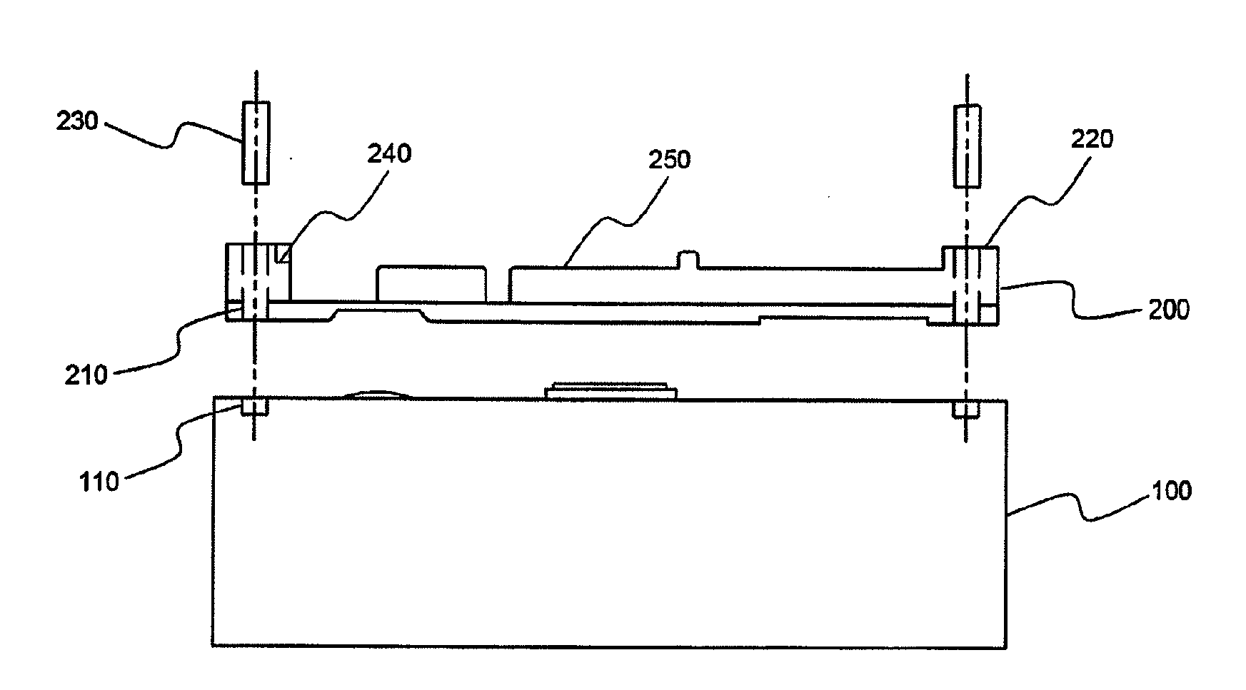
[0084]An insulative mounting member was placed on the top of the battery cell, such that through-holes, formed at the insulative mounting member, were ali...

example 2

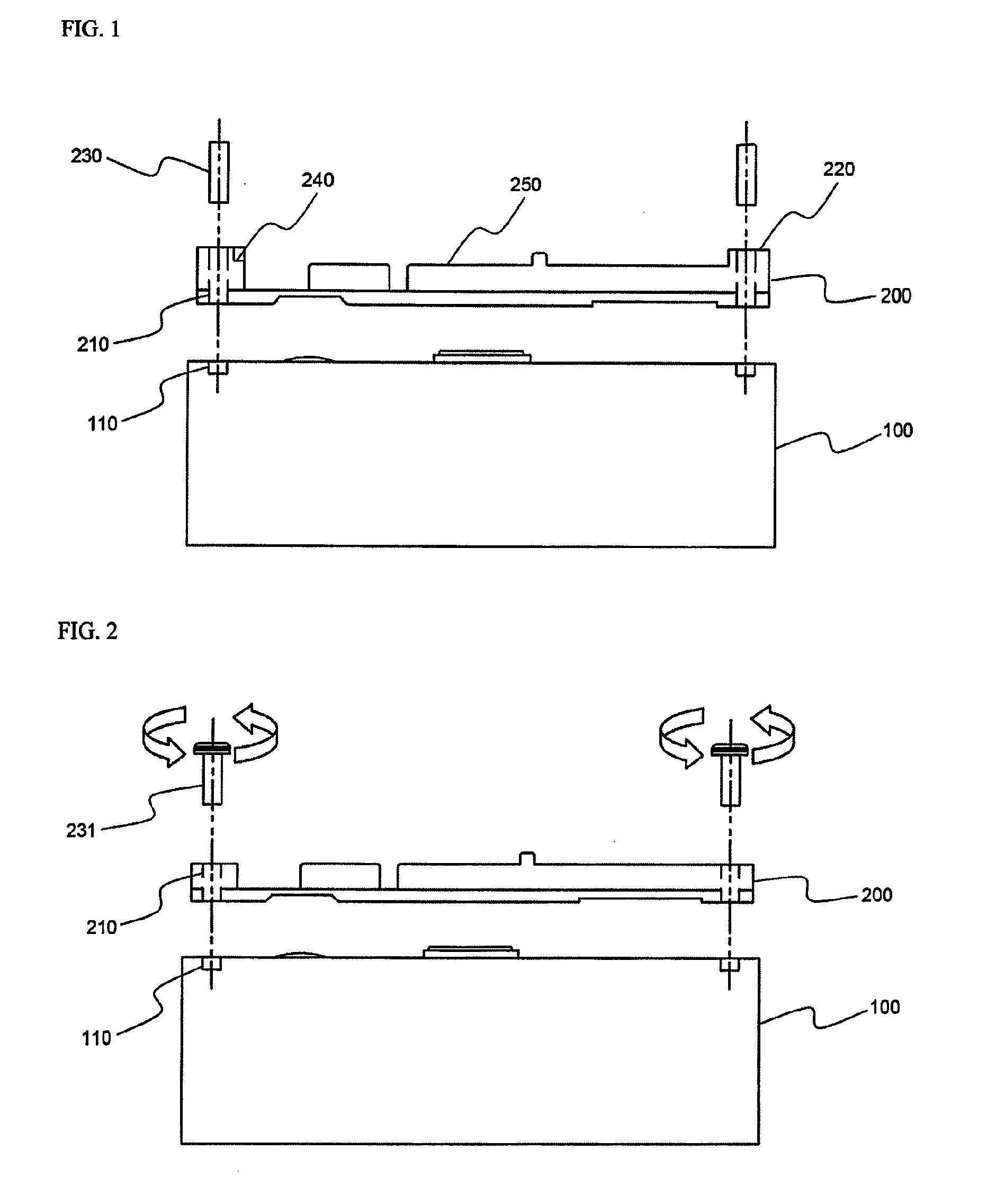
[0086]A secondary battery pack was manufactured in the same manner as Example 1 except that screws, as coupling members, were threadedly inserted into the coupling grooves through the through-holes, as shown in FIG. 1, such that the insulative mounting member was coupled to the battery cell.

experimental example 1

[0088]Bending tests were carried out on 20 battery packs manufactured according to Example 1, 20 battery packs manufactured according to Example 2, and 20 battery packs manufactured according to Comparative example 1, to measure the coupling strength between the battery cell of each battery pack and the insulative mounting member coupled to the battery cell (See FIGS. 14 and 15). Specifically, load applied to the middle of each secondary battery pack was gradually increased, while the top cap and the bottom cap of each secondary battery pack were fixed, to measure the magnitudes of the load when the battery packs broke. The experiment results are indicated in Table 1 below.

TABLE 1Breaking loadComparative(kgf)Example 1Example 2example 1Less than 2500626 to 30001231 to 3500235 to 4500—45 to 5057—50 to 551311—More than 5522—

[0089]As can be seen from Table 1 above, the coupling force of the battery packs manufactured according to Example 1 and Example 2 was greatly improved as compared ...


PUM

PropertyMeasurementUnit
angleaaaaaaaaaa
sizeaaaaaaaaaa
heightaaaaaaaaaa

Abstract

Disclosed herein is a secondary battery pack constructed such that an insulative mounting member is coupled to the top of a battery cell through a specific coupling structure. The secondary battery pack includes a battery cell having an electrode assembly of a cathode / separator / anode structure mounted in a battery case together with an electrolyte in a sealed state, an insulative mounting member having openings, through which electrode terminals of the battery cell are exposed to the outside, the insulative mounting member being constructed in a structure in which a safety element is mounted to the top of the insulative mounting member, the insulative mounting member being in direct contact with the top of the battery cell, and an insulative cap coupled to the top of the battery cell such that the insulative cap surrounds the insulative mounting member while the safety element is mounted to the insulative mounting member The battery case is provided at the top thereof with at least one coupling groove, and the insulative mounting member is provided with at least one through-hole communicating with the at least one coupling groove, whereby the coupling of the insulative mounting member to the battery cell is accomplished by the insertion of at least one coupling member into the at least one coupling groove through the at least one through-hole such that the at least one coupling member is not exposed to the outside of the insulative cap.

Description

FIELD OF THE INVENTION[0001]The present invention relates to a secondary battery pack constructed such that an insulative mounting member is coupled to the top of a battery cell through a specific coupling structure, and, more particularly, to a secondary battery pack including a battery cell having an electrode assembly of a cathode / separator / anode structure mounted in a battery case together with an electrolyte in a sealed state, an insulative mounting member having openings, through which electrode terminals of the battery cell are exposed to the outside, the insulative mounting member being constructed in a structure in which a safety element is mounted to the top of the insulative mounting member, the insulative mounting member being in direct contact with the top of the battery cell, and an insulative cap coupled to the top of the battery cell such that the insulative cap surrounds the insulative mounting member while the safety element is mounted to the insulative mounting me...

Claims


Application Information

Patent Timeline
Patent Type & Authority Applications(United States)
IPC IPC(8): H01M2/02H01M50/528H01M50/119H01M50/147H01M50/296H01M50/55H01M50/562H01M50/572H01M50/583
CPCH01M2/0215H01M2/0285H01M2200/106H01M2/34H01M2200/00H01M2/0404Y02E60/10H01M50/147H01M50/572Y02P70/50H01M50/562H01M50/583H01M50/296H01M50/55H01M50/119H01M50/555H01M50/209H01M10/425
Inventor JUNG, SOONKWANGSONG, SUKJIN
Owner LG ENERGY SOLUTION LTD
Why Eureka
Try Eureka