
Hydro-actuated engine

a technology of hydraulic actuators and engine bodies, applied in the direction of machines/engines, fluid couplings, couplings, etc., can solve the problems of finite quantity, unenvironmental friendly fossil fuels, etc., and achieve the effect of favorable ratio

Inactive Publication Date: 2009-12-31
FRYE CLARENCE EDWARD
View PDF17 Cites 14 Cited by
  • Summary
  • Abstract
  • Description
  • Claims
  • Application Information

AI Technical Summary

Benefits of technology

[0042]The system, being robust and expandable, can easily be designed and fielded as standardized system packages, ranging from miniaturized power versions to either standardized or unique industrial sized versions.

Problems solved by technology

In the present circumstances, our primary source is by fossil-based fuels, which are not environmentally friendly and are finite in quantity.
This creates a vacuum.

Method used


Image

  • Hydro-actuated engine
  • Hydro-actuated engine
  • Hydro-actuated engine

Examples


first embodiment

—FIRST EMBODIMENT

Overview of Invention

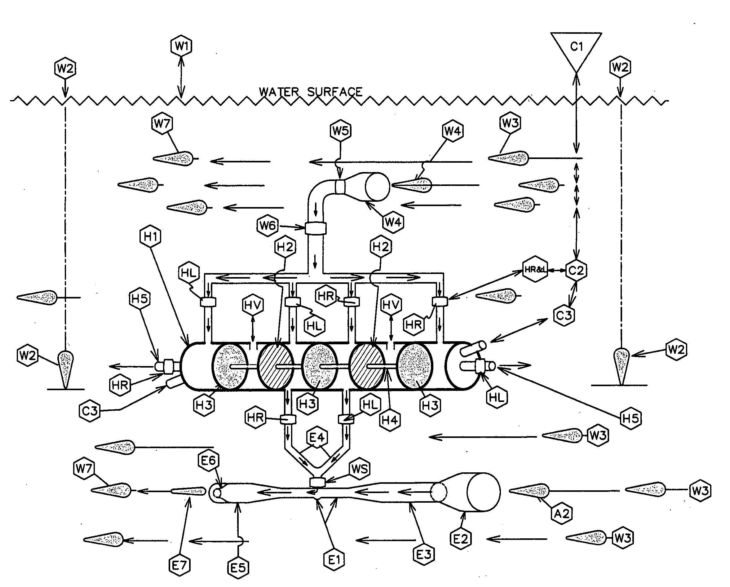
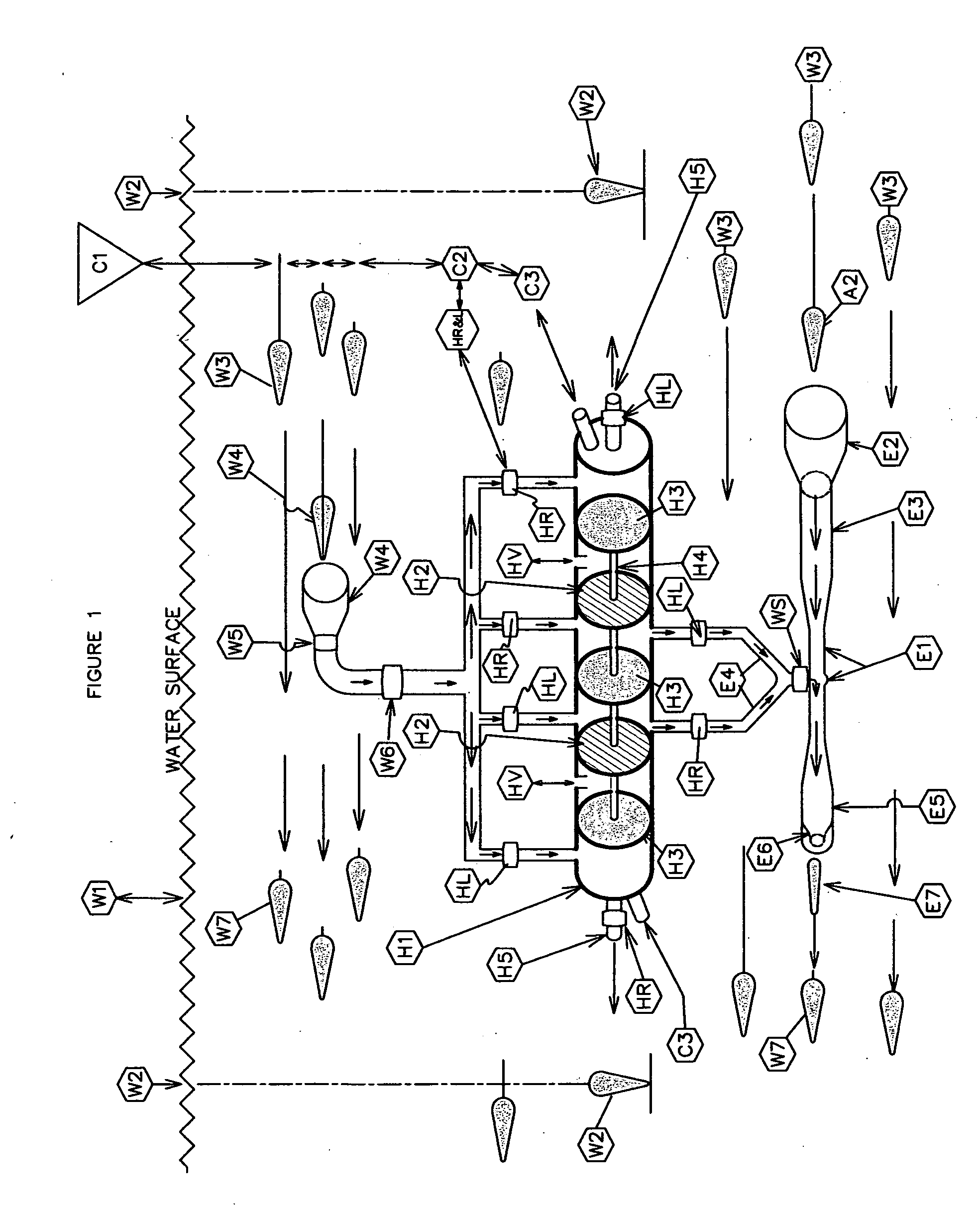
[0084]This invention is in all respects a linear hydraulic motor which can perform all four-cycle engine functions simultaneously. The preferred embodiment, when placed and operated at a depth, within a body of water, is in fact, an infinite molecular power source.

[0085]To begin, the Hydrostatic Engine is positioned in a body of flowing water mass, at a depth and positioned by attachment or tether. The system's shrouded intake ports must be oriented so as to be directly facing the oncoming stream of flowing water. The exit of discharge point faces downstream.

[0086]The water flow passes thru the shrouded input port and flows through the inline replaceable filter and fills the conduit until it applies its restrained force against the four (4) closed solenoid switched valves which control entry into the ports of the three (3) hydraulic cylinder chambers. Two (2) ports open into opposite ends of the center section chamber, which is the power stroke ...


PUM


Abstract

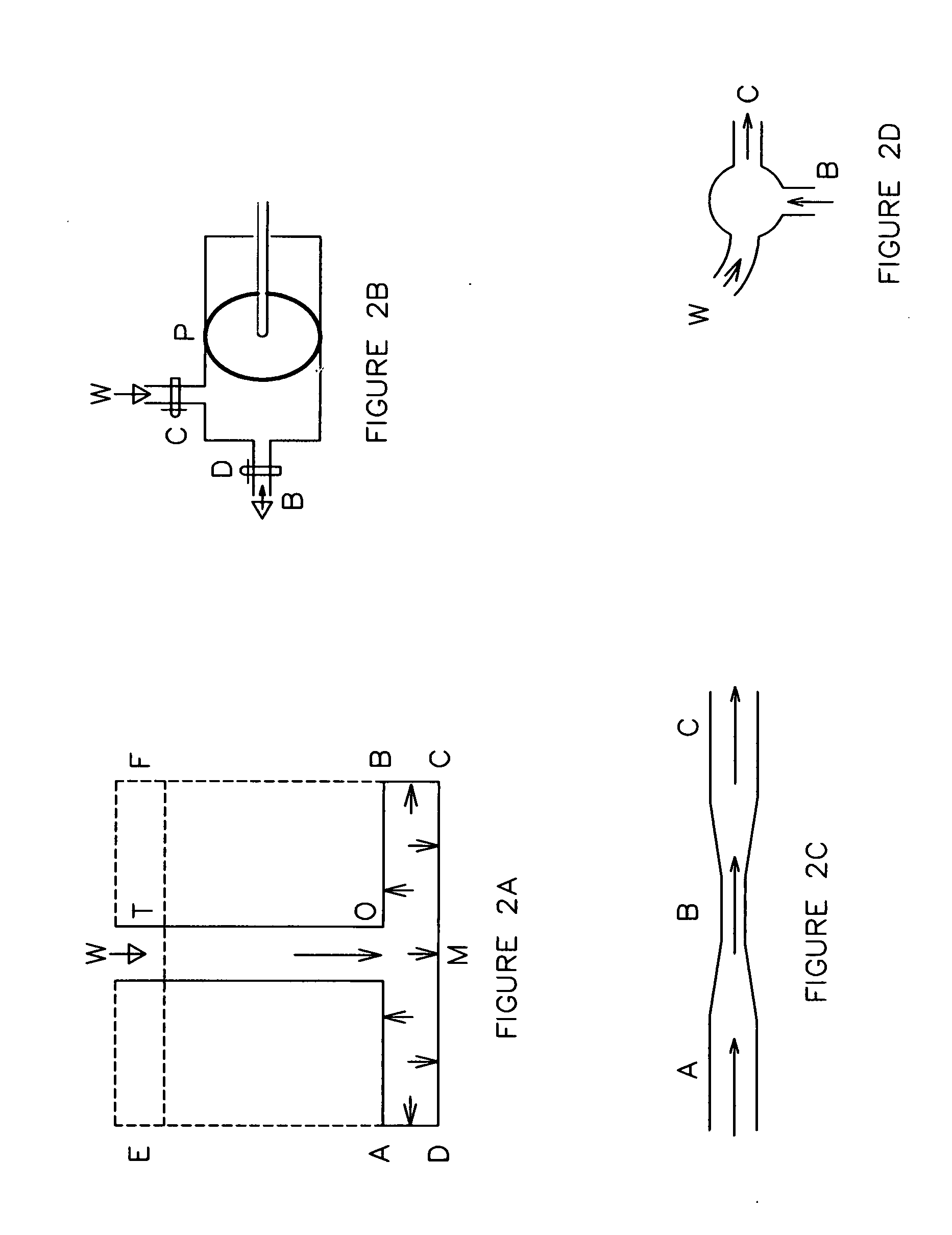
This water powered engine, when submerged deep in a moving body of water, functions as a four cycle engine, with water as it prime mover. It is a linear motor, just as if it were powered by ordinary fossil-based fuels. This invention harnesses the force of moving water and the pressure of water at a depth and creating a prime mover to power electrical generators or to do other work. When water is confined in a solid body and its force is applied to the surface of a piston, that force is transmitted equally, in all directions throughout the fluid or gas in the form of pressure. This characteristic is known as “Pascal's Law”. The component parts of this linear motor are a hydraulic cylinder, positive displacement pumps, a Venturi / Eductor vacuum assembly, an electronic piston positioning sensors, solenoid controlled valves and process program software. It is positioned to face an oncoming downstream water force. It may be either singular or in plurality as an array, this being a site adaptation design issue. Its purpose is to transform the limitless energy from moving water. It is an integration of existing technology of various fields. It is applicable to any comparable moving fluid source, particularly water. The coastal Gulf Stream and other ocean currents provide ideal environments as infinite sources of renewable energy.

Description

CROSS REFERENCE TO RELATED APPLICATIONS[0001]This application claims all the benefit of the following U.S. Provisional Application Nos.No. 61 / 213,24720 May 2009HYDROSTATIC ENGINENo. 61 / 195,40107 Oct. 2008HYDROSTATIC ENGINENo. 61 / 129,46830 Jun. 2008HYDROSTATIC ENGINENo. 61 / 136,18418 Aug. 2008HYDROSTATIC ENGINEFEDERALLY SPONSORED RESEARCH RELATED APPLICATIONS[0002]Not ApplicableFOREIGN APPLICATION PRIORITY DATABACKGROUND—FIELD[0003]This application relates to a linear motor submerged deep in a moving body of water, using natural motive forces of nature to produce hydropower, which could be used in the generation of electrical energy, utilizing the technologies of hydraulics and the Venturi Principle.PRIOR ART REFERENCES[0004]Applicant is aware of the following U.S. Patents and Patent Application pertaining to water powered devices and the like. None of the citations, however, discloses a power system having the functional features or the capabilities of the present invention.PATENTS4,...

Claims


Application Information

Patent Timeline
IPC IPC(8): F03B13/00
CPCF03B13/148F03B17/06Y02E10/38F05B2240/97Y02E10/28F03G7/04Y02E10/30Y02E10/20
Inventor FRYE, CLARENCE EDWARD
Owner FRYE CLARENCE EDWARD
Learn More