Detection method, detection apparatus, and sample cell and kit for detection

a detection apparatus and sample cell technology, applied in the direction of optical radiation measurement, fluorescence/phosphorescence, nuclear engineering, etc., can solve the problems of variable intensity of signals, different signals from fluorescent labels, and inefficient use of electric fields, so as to prevent variation in the intensity of signals and efficiently use electric fields

Inactive Publication Date: 2009-12-31
FUJIFILM CORP
View PDF10 Cites 24 Cited by
  • Summary
  • Abstract
  • Description
  • Claims
  • Application Information

AI Technical Summary

Benefits of technology

[0063]According to the detection method and apparatus of the present invention, the magnetic microparticle is added to the fluorescent-label binding substance that binds to the sensor portion based on the amount of the detection target substance contained in the sample. Further, the fluorescent label contained in the fluorescent-label binding substance is excited and the amount of light generated by the excitation is detected in a state in which the fluorescent-label binding substance is attracted to the surface of the sensor portion by the magnetic field application means. Since the light is detected while the fluorescent-label binding substance is attracted to the surface of the sensor portion, it is possible to efficiently use the electric field on the surface of the sensor portion at which the degree of enhancement of the electric field is high. Further, since it is possible to make the distance from the surface of the fluorescent label uniform (even), variation in the intensity of signals can be prevented. In other words, it is possible to detect stable signals at an excellent S / N ratio, and to accurately detect presence and / or the amount of the detection target substance.
[0064]When the sample cell for detection of the present invention or the kit for detection of the present invention is used, it is possible to easily perform the detection method of the present invention. Further, it is possible to effectively use the enhanced electric field, and to prevent variation in the intensity of signals. Further, it is possible to accurately detect presence and / or the amount of the detection target substance.

Problems solved by technology

Therefore, there is a problem that when the distance from the surface to the fluorescent label changes even slightly, signals from the fluorescent labels become different from each other, and varied.
Hence, a similar problem that the intensity of the signal is varied exists.

Method used


Image

  • Detection method, detection apparatus, and sample cell and kit for detection
  • Detection method, detection apparatus, and sample cell and kit for detection
  • Detection method, detection apparatus, and sample cell and kit for detection

Examples


first embodiment

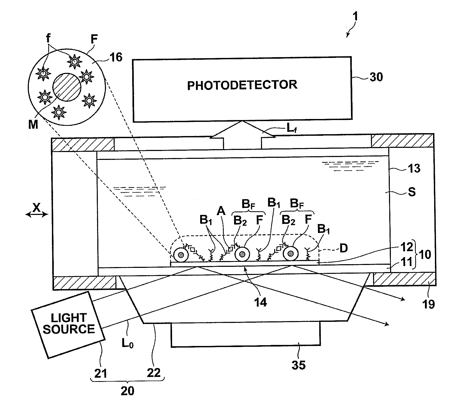
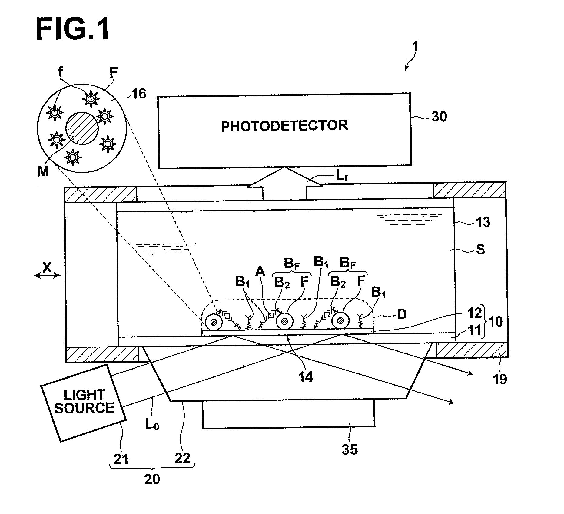
[0111]A detection method and apparatus according to a first embodiment will be described with reference to FIG. 1. FIG. 1 is a schematic diagram illustrating the structure of the whole detection apparatus of the first embodiment. The detection method and apparatus in this embodiment enhances an electric field by surface plasmon resonance, and detects fluorescence excited in the enhanced electric field.

[0112]In the fluorescence detection method of the present embodiment, a sensor chip 10 including a dielectric plate 11 and a sensor portion 14 that has a metal layer 12 deposited in a predetermined area on a surface of the dielectric plate 11 is used.

[0113]In the sensor chip 10, a metal film (thin-film, coating or the like), as the metal layer 12, is deposited on a predetermined area on a surface of the dielectric plate 11, such as a glass plate. The metal film (layer) 12 may be formed on a surface of the dielectric plate 11 by forming (placing) a mask that has an opening in the predet...

second embodiment

[0127]A detection method and apparatus according to a second embodiment will be described with reference to FIG. 4. FIG. 4 is a schematic diagram illustrating the structure of the whole detection apparatus of the second embodiment. The detection method and apparatus in this embodiment enhances an electric field by localized plasmon resonance, and detects fluorescence excited in the enhanced electric field. In the following descriptions, the same reference numerals will be assigned to elements corresponding to the elements in the first embodiment.

[0128]In a fluorescence detection apparatus 2 illustrated in FIG. 4, a sensor chip 10′ and an excitation light irradiation optical system 20′ differ from the elements of the fluorescence detection apparatus 1 of the first embodiment.

[0129]The sensor chip 10′ includes, as a metal layer 12′ provided on the dielectric plate 11, a metal fine structure body or a plurality of metal nanorods, which generate so-called localized plasmons by irradiati...

third embodiment

[0143]A detection method and apparatus according to a third embodiment will be described with reference to FIG. 6. FIG. 6 is a schematic diagram illustrating the structure of the detection apparatus of the third embodiment. The detection method and apparatus in this embodiment enhances an electric field by surface plasmon resonance, and fluorescence excited in the enhanced electric field newly induces plasmons in the metal layer. Further, light from the newly-induced plasmons radiates from the opposite surface of the dielectric plate, the opposite surface being opposite to the metal-layer-formation surface of the dielectric plate. Further, radiation light from the newly induced plasmons is detected in the radiation light detection method and apparatus of this embodiment.

[0144]In a radiation light detection apparatus 3, illustrated in FIG. 6, the arrangement of the fluorescence detection apparatus and the photodetector is different from the arrangement in the first embodiment. In the...


PUM

PropertyMeasurementUnit
distanceaaaaaaaaaa
sizeaaaaaaaaaa
sizeaaaaaaaaaa

Abstract

A sensor chip includes a sensor-portion having at least a metal-layer deposited on a surface of a dielectric-plate. A fluorescent-label binding-substance in an amount corresponding to the amount of a detection target substance in a sample binds to the sensor-portion when the sample is placed in contact with the sensor-portion. The sensor-portion is irradiated with excitation-light to generate an enhanced electric-field on the sensor-portion. The amount of the detection target substance is detected based on the amount of light generated by excitation of a fluorescent-label in the fluorescent-label binding-substance in the enhanced electric-field. A magnetic-particle is added to the fluorescent-label binding-substance, and the amount of the detection target substance is detected while the fluorescent-label binding-substance modified with the magnetic-particle is attracted to the vicinity of the sensor-portion by a magnetic-field application means arranged on an opposite-surface side of the dielectric-plate, opposite to the metal-layer-deposited surface thereof.

Description

BACKGROUND OF THE INVENTION[0001]1. Field of the Invention[0002]The present invention relates to a detection method, a detection apparatus, a sample cell for detection and a kit for detection to detect a substance to be detected (a detection target substance) in a sample.[0003]2. Description of the Related Art[0004]Conventionally, in the field of bio-measurement and the like, a fluorescence detection method is widely used as a highly accurate and easy measurement method. In the fluorescence detection method, a sample that is presumed to contain a detection target substance that outputs fluorescence by being excited by irradiation with light having a specific wavelength is irradiated with excitation light having the specific wavelength. At this time, fluorescence is detected to confirm the presence of the detection target substance. Further, when the detection target substance is not a phosphor (fluorescent substance), a substance that has been labeled with a fluorescent dye and that...

Claims


Application Information

Patent Timeline
Patent Type & Authority Applications(United States)
IPC IPC(8): G01N21/64G01N21/05G01N21/76
CPCG01N21/05G01N21/6428G01N21/648G01N2021/0346G01N33/54333G01N33/54373G01N2021/6482G01N33/54306
Inventor OHTSUKA, HISASHI
Owner FUJIFILM CORP
Why Eureka
Try Eureka