
Method of processing rock with laser and apparatus for the same

Active Publication Date: 2010-01-07
JAPAN DRILLING CO LTD +2
View PDF5 Cites 53 Cited by
  • Summary
  • Abstract
  • Description
  • Claims
  • Application Information

AI Technical Summary

Benefits of technology

[0025]The liquid used in the present invention may be clear or may be opaque. Although any kind of liquid can be used, using water is the easiest and most practical.
[0031]As the laser, a fiber laser (1.3 to 1.5 μm wavelength), a coil laser (1.3 μm wavelength) or the like may be used as long as the laser has a high factor of absorption into liquid. Preferably, a semiconductor laser having a long wavelength, such as one selected from a group of a CO2 laser, a CO laser, an Er-YAG laser and a Ho-YAG laser may be used. These lasers have wavelengths of 2.0 μm or longer and can produce high power.
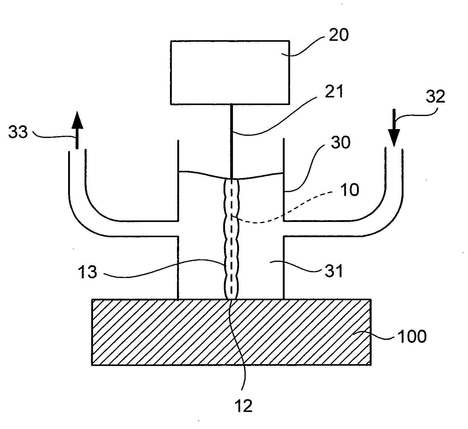
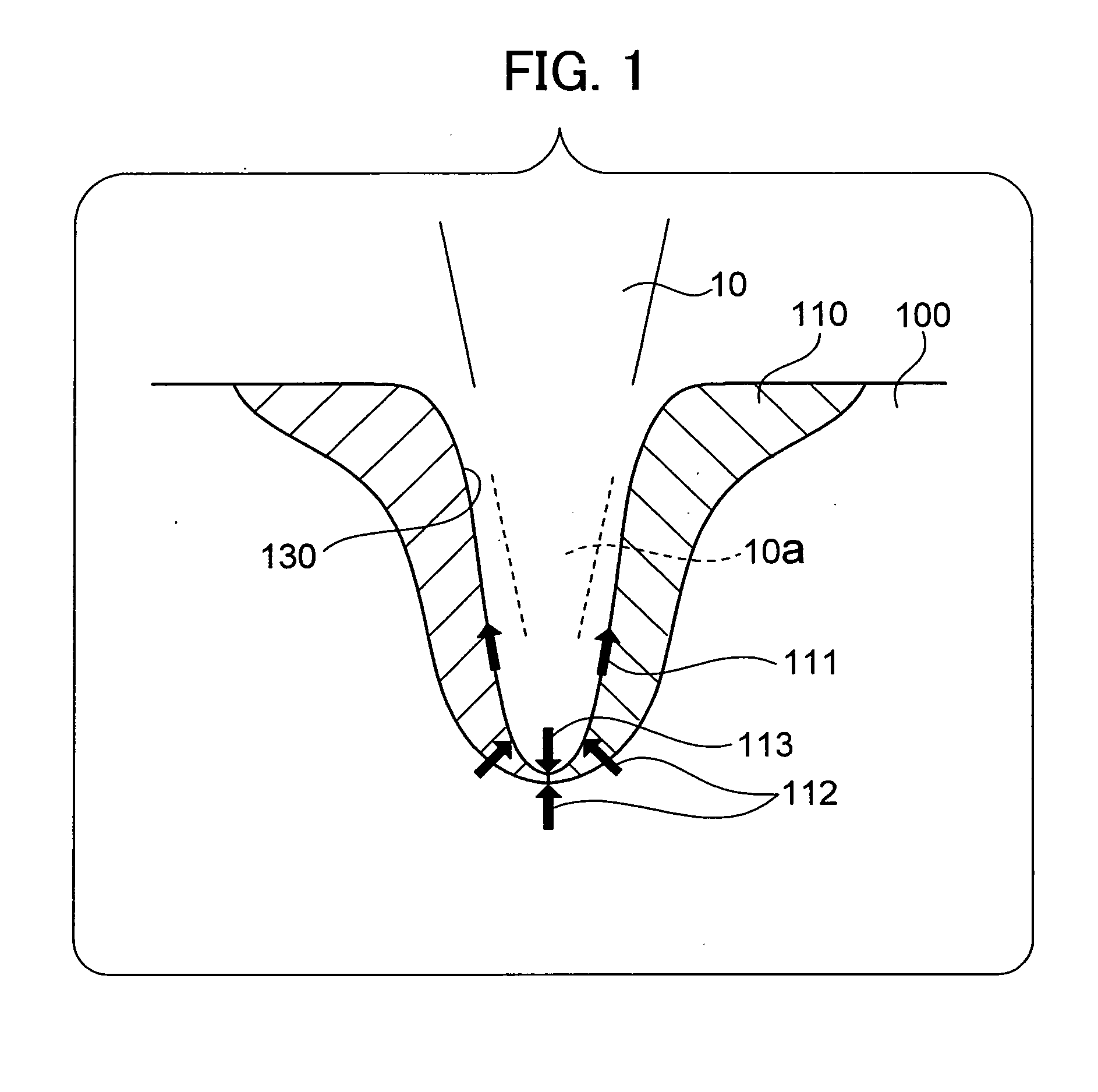
[0035]A feature of the present invention is to remove molten dross generated in a cavity created in rock, by using a laser having a high factor of absorption into liquid, and to thereby prevent the dross from hardening in the borehole.
[0036]According to the method of the present invention, by covering the laser irradiation position with liquid and using a laser having a high factor of absorption into the liquid, deposited dross can be effectively removed, and the boring and cutting of rock can be facilitated.
[0037]Moreover, by using the apparatus of the present invention, the method of the present invention can easily be implemented.
[0038]Conventionally, the processing of rock having a high content of quartz glass or silicon dioxide by means of a laser has been difficult. With the present invention, the processing of such rock can be easily performed. Naturally, the processing of rock having a low content of quartz glass or silicon dioxide or quarts-glass-free and / or silicon-dioxide-free rock can also be easily performed by using the method of the present invention.

Problems solved by technology

A laser having a wavelength shorter than 1.2 μm has a low factor of absorption into liquid, and is thus not suitable here.

Method used


Image

  • Method of processing rock with laser and apparatus for the same
  • Method of processing rock with laser and apparatus for the same
  • Method of processing rock with laser and apparatus for the same

Examples


example

[0075]Boring was performed on a block of Inada granite by laser working. The properties of the target granite are as follows.

[0076]Thermal conductivity: 0.13 to 0.2 (cal / cm / s / cdeg)

[0077]Mineral Composition:

Plagioclase22 wt %Quartz42 wt %Biotite 4 wt %

[0078]Chemical Composition:

SiO277.65 wt % TiO20.19 wt %Al2O312.55 wt % Fe2O30.46 wt %FeO0.98 wt %MnO0.08 wt %MgO0.18 wt %CaO1.44 wt %

[0079]The used laser is as follows.

[0080]Laser type: CO2 laser

[0081]Laser wavelength: 10.6 μm

[0082]Laser output: 5 kW

[0083]Liquid: two kinds, water and 4% by weight bentonite solution (opaque)

[0084]Laser irradiation direction: upper surface of target

[0085]By using the apparatus schematically shown in FIG. 5, laser irradiation was performed for 2 minutes. After the irradiation, it was observed that the fine pieces formed from dross was scattered in the water or the bentonite solution. After the irradiation, it was confirmed that a borehole having a diameter of approximately 15 mm and a maximum depth of appr...


PUM

PropertyMeasurementUnit
Wavelengthaaaaaaaaaa
Pressureaaaaaaaaaa

Abstract

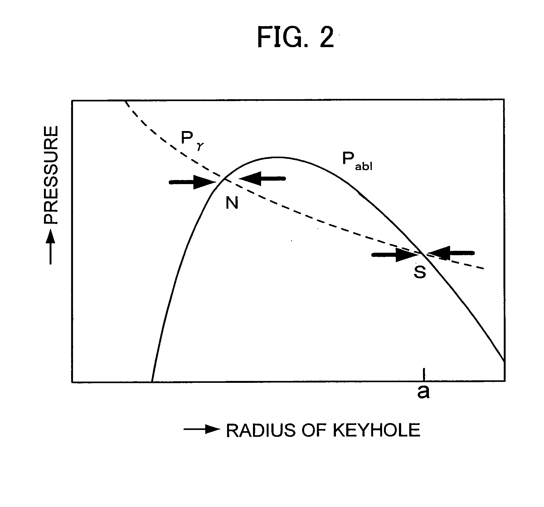
An object is to provide a method capable of boring a borehole even when quartz glass or silicon dioxide is deposited as molten dross by laser irradiation. A laser irradiation position of a workpiece is irradiated with a laser having wavelength of 1.2 μm or longer and a high factor of absorption into liquid, for example, a CO2 laser, from a laser oscillator through liquid. By high pressure generated in an advancing microbubble flow occurring in the liquid, molten dross is scattered. Thus, the processing, such as boring, of the rock is performed.

Description

TECHNICAL FIELD[0001]The present invention relates to a method of processing rock with a laser and an apparatus therefor. More specifically, the present invention relates to a technique for processing rock with a laser without any problem even when dross is deposited in working the rock.BACKGROUND ART[0002]Research has been carried out on the boring and processing of rock with a laser (see, for example, Patent Document 1).[0003]When rock is continuously irradiated with a laser, the rock melts and dross is generated, causing a problem that the dross hinders processing the rock with the laser. In the above technique, to prevent dross from being built up and to thereby avoid hindering the progress in processing the rock, assist gas is blown onto a laser irradiated part to encourage discharge of the dross.[0004]Moreover, when being rapidly and locally heated, some kinds of rock are easily destroyed and other kinds of rock are hardly destroyed, depending on various factors such as the ki...

Claims


Application Information

Patent Timeline
IPC IPC(8): G01V5/00B23K26/00B23K26/12B28D1/14H01S3/17H01S3/30
CPCB23K26/381B23K26/1417B23K26/4075B23K26/382B23K26/146B23K26/40B23K2103/50
Inventor KOBAYASHI, TOSHIOTAKAYAMA, KAZUYOSHIOHTANI, KIYONOBUUMEZU, SATORU
Owner JAPAN DRILLING CO LTD
Learn More