

Implantable voltaic cell
a voltaic cell, battery technology, applied in the field of implantable batteries, can solve the problems of inadequate monitoring of blood sugar, unpalatable daily monitoring regimen, and inability to tolerate patients, and achieve the effect of improving the patient's health, and improving the patient's overall health
- Summary
- Abstract
- Description
- Claims
- Application Information
AI Technical Summary
Benefits of technology
Problems solved by technology
Method used
Image

Examples
example 1
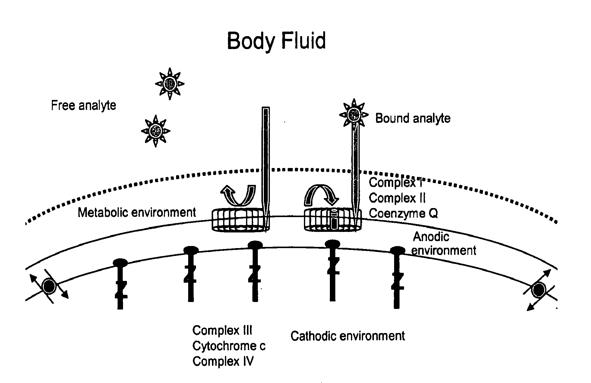
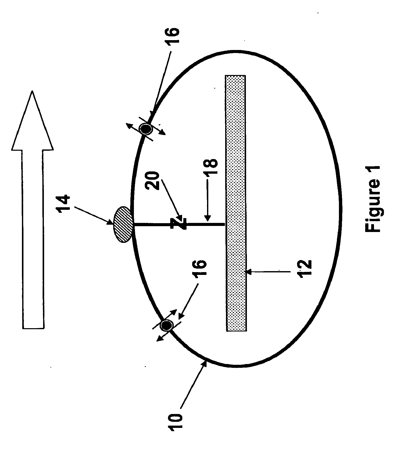
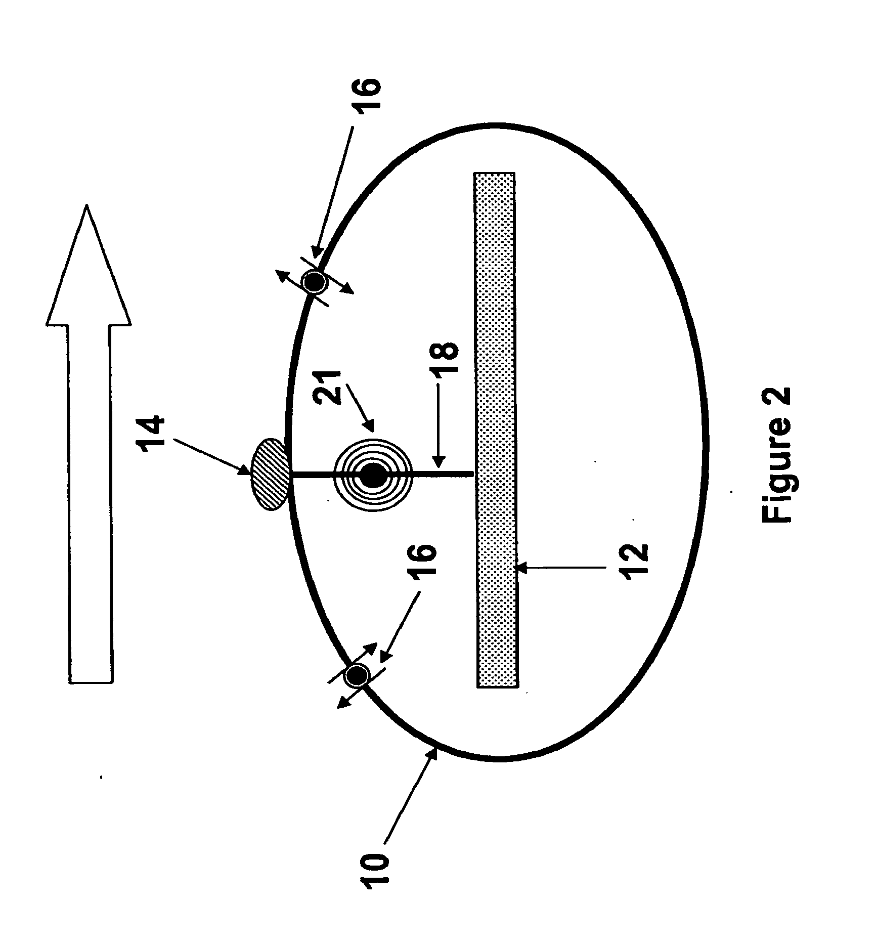
[0135]In an embodiment of the invention, the shell contains a non-magnetic cathode (such as silver) in an aqueous ammonia solution. A non-magnetic wire connects the cathode to an anode outside of the shell (to prevent short-circuiting of the cell and abolition of current generation). The summed electric potential of the reaction (Eo=0.323 V) represents the overall thermodynamic favorability of the reaction of the oxidation of glucose and the reduction of Ag+ from the aqueous dianuninesilver complex [Ag(NH3)2+] in solution to elemental silver (pure silver metal).
[0136]The oxidization of glucose is a highly thermodynamically favorable reaction because of the high potential chemical energy stored in carbohydrates (it is precisely because of this that glucose is the body's primary means of generating energy for life). It is through the voltaic mechanism described above that the chemical energy is converted to electric energy. Thus, as blood flows around (or through, in the case of tubul...
example 2
[0145]A voltaic cell glucometer of the invention is subcutaneously implanted into a diabetic patient who is able to monitor and regulate his or her own insulin levels. The glucometer emits radiowaves which continuously monitor the patient's glucose levels. The signal is received by a radio receiver worn as a wristwatch-type receiver that displays the patient's blood glucose level. The wristwatch receiver also displays the time of day and is equipped with an alarm to alert the patient when his or her glucose level drops to a point at which the patient becomes hypoglycemic, or when an insulin does is required to treat or prevent hyperglycemia.
Example 3
[0146]A voltaic cell glucometer of the invention is subcutaneously implanted into a diabetic patient who is unable to monitor and regulate his or her own insulin levels. The patient is an incapacitated person in the hospital. The glucometer emits radiowaves which continuously monitor the patient's glucose levels. The signal is received ...
example 3
[0147]A voltaic cell having cholesterol oxidase complexed to the surface of the anode of the voltaic cell is implanted into a patient having severe hypercholesterolemnia. The voltaic cell is in contact with the patient's blood and cholesterol flowing past the anodes of the cell is oxidized and the electrons flow through the connector to the cathode within the shell of the voltaic cell. The current generated is converted to high frequency radio waves which are received by an external radio receiver which is programmed and calibrated to calculate and display the patient's blood cholesterol level. The patient's cholesterol level is monitored to assess the patient's response to dietary restrictions and therapy with cholesterol-lowering drugs, to help prevent heart attacks and strokes.
PUM
 Abstract
Description
Claims
Application Information