[0021]In one embodiment, the fluid
insertion path and the fluid extraction path are in communication with the inside of the inflatable balloon. The distal end of the cannula desirably includes a vent hole or vent opening disposed inside the inflatable balloon. The vent hole is desirably surrounded by and located adjacent a proximal end of the inflatable balloon, whereby the fluid insertion and fluid extraction paths are in communication with the vent hole. In one embodiment, during a priming operation, the balloon at the distal end of the catheter is pointed downward so that the vent hole is located at the highest point of the balloon. Positioning the vent hole at the highest point during priming facilitates the removal of air first and fluid second to achieve a good priming result whereby the balloon is filled with fluid and all air or gas has been removed from inside the balloon. In one embodiment, the vent hole for extracting the air or gas from the balloon may be separate from a conduit used for introducing fluid into the balloon and extracting fluid from the balloon.
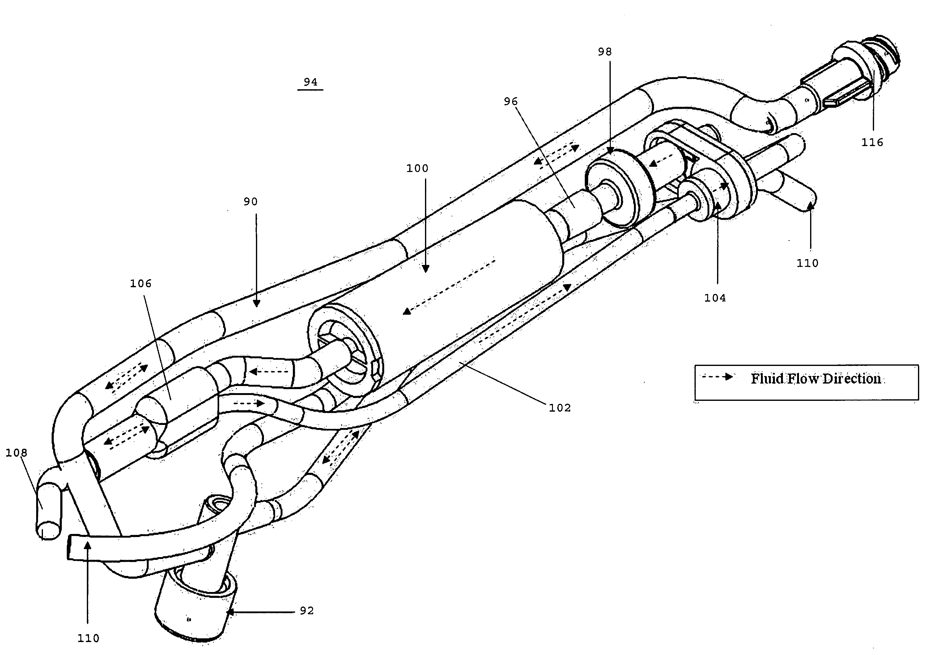
[0030]Although the present invention is not limited by any particular theory of operation, it is believed that providing a degassing system including paired one-way check valves and an
air filter assembly in communication with one of the check valves provides a unique arrangement to control the fluid flow path between a fluid source and an inflatable balloon. The specific arrangement of the opposing check valves enables the fluid to flow into the inflatable balloon while removing any gas or air present in the fluid. The fluid insertion path and the fluid extraction path provide two separate and distinct fluid flow paths through the balloon catheter. Separating the fluid extraction path from the fluid insertion path enables the fluid to be extracted from the balloon without passing through the first
check valve and the
air filter of the fluid insertion path. This situation exists for both automated and emergency / manual
modes of operation. The above configuration of the degassing system protects the membrane of the filter from undesired stress during fluid extraction. In one embodiment, there is only one single fluid inlet tube that leads to the degas system and only one single outlet tube at the
discharge end of the degas system, whereby only the degas system has two distinct fluid paths (e.g. a fluid insertion path and a fluid extraction path). This preferred design is compact, minimizes the size of the catheter, and eliminates the need for another tube.
[0034]In one embodiment, the cannula includes a lumen extending between the proximal and distal ends thereof for introducing a fluid into the inflatable balloon. A pressure monitor may be in communication with the lumen and / or the fluid for monitoring
fluid pressure inside the inflatable balloon. The cannula may also include an
impeller drive shaft extending therethrough that is coupled with the
impeller for rotating the
impeller. The
drive shaft preferably has a distal end that extends beyond a distal end of the impeller and a protective cap may cover the distal end of the
drive shaft for spacing the distal end of the drive shaft and the impeller from the inflatable balloon. The spacing provided by the cap may prevent the balloon from becoming damaged by contacting the rotating drive shaft or the rotating impeller. In one embodiment, the protective cap is insertable into an opening at the distal end of the elongated tube. The protective cap may be insertable into the fluid outlet located at the distal end of the elongated heating tube. The protective cap preferably has one or more openings extending therethrough for enabling fluid to pass by the cap when the cap is secured in place.
[0037]In one embodiment, once a balloon catheter is positioned within a
uterine cavity, fluid is introduced into the inflatable balloon. The fluid is heated, preferably by a heating tube, and circulated within the
uterine cavity to heat the lining of the cavity to sufficiently damage the endometrial lining. The heater tube desirably has one or more films coated over the outer
diameter of the tube that are adapted to generate heat. An impeller is located along the inner
diameter of the heater tube to circulate the fluid. The arrangement of the impeller relative to the heater tube positively ensures that the circulated fluid will pass by the inner
diameter surface of the heater tube, which allows the fluid to more effectively absorb heat for reducing the heater temperature
set point to heat the fluid to a certain temperature in comparison to the arrangement of having an
agitator at the distal end of the heater. Moreover, as a result of fluid being positively moved through the heater, the fluid within the balloon is more efficiently heated and circulated, thereby resulting in a more consistent balloon surface temperature.
[0038]In one embodiment of the present invention, a balloon catheter has an impeller located along the inner diameter of a heating
assembly, such as a heating assembly having an elongated heating tube. Although the present invention is not limited by any particular theory of operation, it is believed that the arrangement of the impeller relative to the heating assembly improves overall
fluid circulation inside the balloon, which improves
thermal transfer from the heater to the fluid, and which results in uniform temperature distribution around the outer surface of the balloon. The more uniform temperatures around the outer surface of the balloon promote more uniform treatment of the
uterine tissue. In addition, the improved
heat transfer between the heating assembly and the fluid results in a reduction in the amount of energy required to heat the fluid. Moreover, better
heat transfer enables the system to have a reduced temperature
set point while still achieving an appropriate temperature at the outer surface of the balloon.

