Integrated circuit device with improved underfill coverage

a technology of integrated circuits and underfills, applied in semiconductor devices, semiconductor/solid-state device details, electrical apparatus, etc., can solve problems such as reliability degradation, failure to remove solder mask layers, and failure to meet the requirements of the application, so as to reduce the likelihood of interfacial failure, and increase the height of the gap

Inactive Publication Date: 2010-01-14
TEXAS INSTR INC
View PDF3 Cites 30 Cited by
  • Summary
  • Abstract
  • Description
  • Claims
  • Application Information

AI Technical Summary

Benefits of technology

[0005]A properly formed underfill between an IC die and a workpiece is typically a requirement for reducing the likelihood of interfacial failure in the flip-chip packaging system. That is, the underfill material typically needs to substantially fill in the entire in the space between the IC die and the workpiece (e.g. PCB) surface to provide a reliable flip chip package. Particularly in the case of Au—Au bonding technology, a narrow gap between the bottom of the IC die and top surface of workpiece can result after bonding. Such narrow gaps increase the challenge of the underfill flow underneath the IC die, generally producing underfill voids in tight areas concentrated mostly in the center of the package under the die, leading to reliability failures. One solution can be to remove the solder mask layer from the workpiece top side surface in areas under the IC die since this increases the height of the gap between the IC die and the workpiece.
[0006]However, removal of the solder mask layer is not always desirable and can cause reliability degradation due to delamination between the workpiece and the underfill or poor electrical contact between an IC die and the workpiece. For example, a solder mask layer typically functions as an adhesion promoter, as adhesion between underfill materials and the solder mask layer is typically greater than that between underfill layers and typical workpiece materials. The solder mask provides passivation of exposed workpiece metals and removing the protective solder mask layer can lead to oxidation of exposed oxidizable metals, such as coppers which can other wise result in poor adhesion between the underfill and the workpiece. The solder mask layer can also control controlling reflow and guide additional plating of contact pads. That is, the solder mask can additional plating of workpiecce contact pads and keep any reflow solder and / or underfill in place.
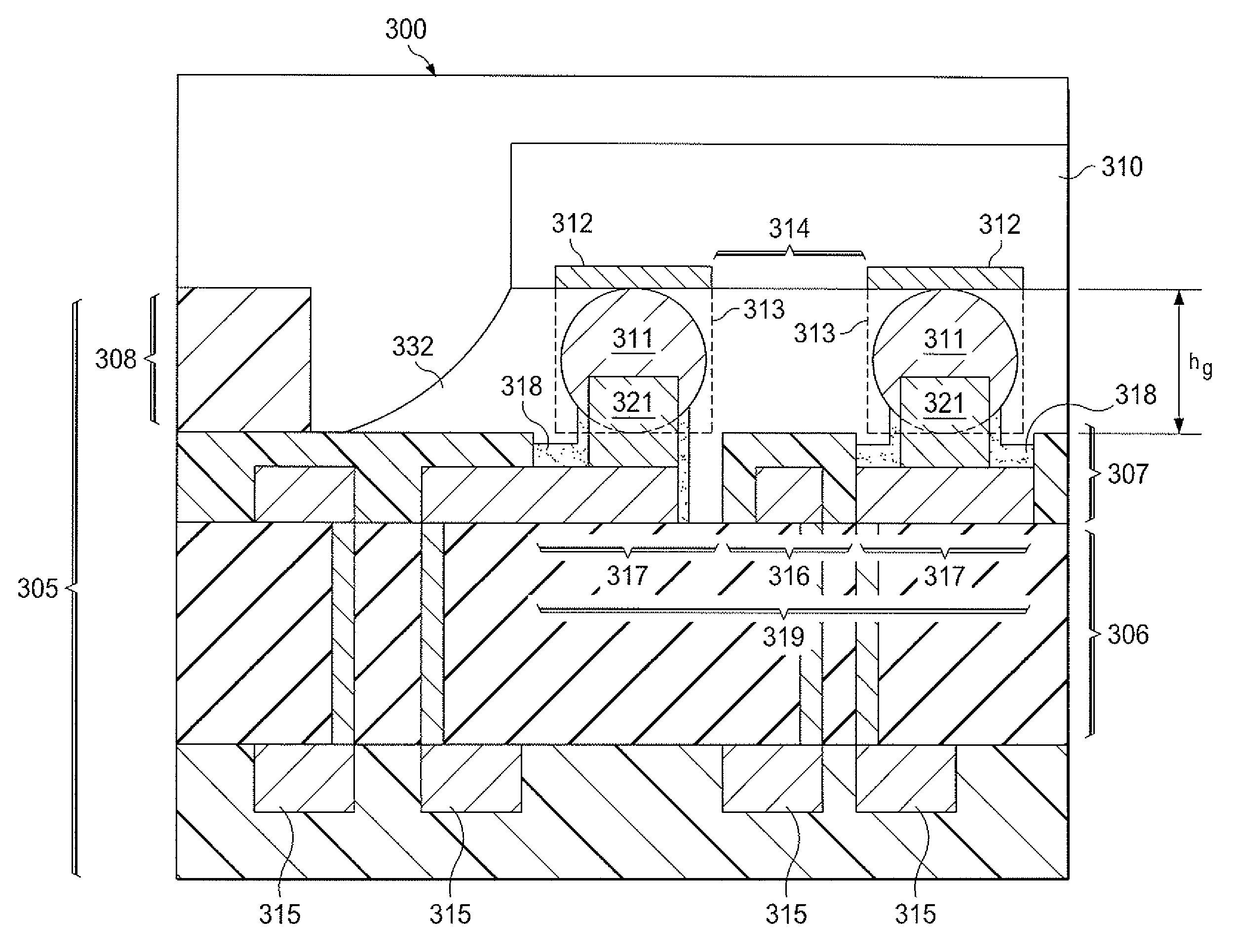
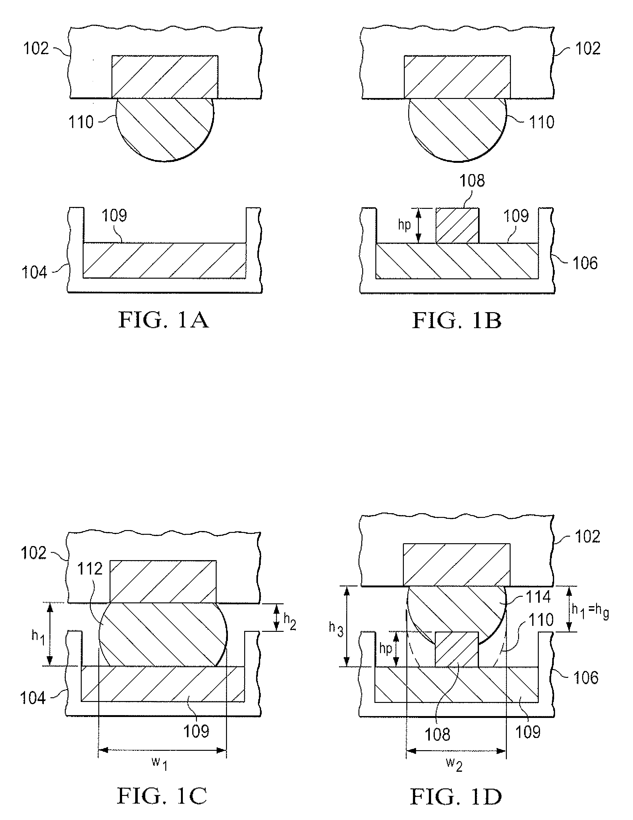
[0007]To avoid removal of the solder mask layer from the workpiece, embodiments of the present invention provide for forming structures which extend upward from the metal contact pads on the workpiece surface, hereinafter referred to as “pedestal structures”. The pedestal structures can be formed in areas of the metal contact pads of the workpiece surface corresponding to the areas of IC die having bump pads. As a result, portions of these bumps are instead bonded to and / or collapsed on the elevated pedestal structures, resulting in an increased final height for the bump pads and the contact pads on the workpiece. Consequently, an increased gap between the IC die and the workpiece is provided which reduces the challenge of underfilling this gap between the IC die and the workpiece. The increased gap generally reduces the amount of underfill voids in tight areas including areas near the center of the IC die area, leading to improved reliability.

Problems solved by technology

Such narrow gaps increase the challenge of the underfill flow underneath the IC die, generally producing underfill voids in tight areas concentrated mostly in the center of the package under the die, leading to reliability failures.
However, removal of the solder mask layer is not always desirable and can cause reliability degradation due to delamination between the workpiece and the underfill or poor electrical contact between an IC die and the workpiece.
The solder mask provides passivation of exposed workpiece metals and removing the protective solder mask layer can lead to oxidation of exposed oxidizable metals, such as coppers which can other wise result in poor adhesion between the underfill and the workpiece.
This smaller gap can cause reliability problems when h2 is less than a minimum height necessary for flowing an adequate flow of underfill material between the IC die 102 and the workpiece 104.
An inadequate flow of underfill material through the gap between the IC die 102 and the workpiece can result in voids, poor adhesion, and possible delamination.

Method used


Image

  • Integrated circuit device with improved underfill coverage
  • Integrated circuit device with improved underfill coverage
  • Integrated circuit device with improved underfill coverage

Examples


Embodiment Construction

[0013]The present invention is described with reference to the attached figures, wherein like reference numerals are used throughout the figures to designate similar or equivalent elements. The figures are not drawn to scale and they are provided merely to illustrate the instant invention. Several aspects of the invention are described below with reference to example applications for illustration. It should be understood that numerous specific details, relationships, and methods are set forth to provide a full understanding of the invention. One having ordinary skill in the relevant art, however, will readily recognize that the invention can be practiced without one or more of the specific details or with other methods. In other instances, well-known structures or operations are not shown in detail to avoid obscuring the invention. The present invention is not limited by the illustrated ordering of acts or events, as some acts may occur in different orders and / or concurrently with o...


PUM


Abstract

An integrated circuit device (300) includes a functional integrated circuit (IC) die (310) having a top IC surface with IC non-contact regions (313) and a plurality of electrically conductive bump pads (311, 312, 313) at pad locations. In the IC (310), at least one of the bump pads (311, 312, 313) extends outward from beyond the IC non-contact regions (313). The integrated circuit device (300) can also include a workpiece (305) having a top workpiece surface comprising at least one die attach area (319) for attaching the IC die (310). The die attach area (319) can include non-contact regions (316) and a plurality of electrically conductive contact pads (317) recessed relative to the non-contact regions (316), where the contact pads (317) face the top IC surface and match the pad locations (312). In the die attach area (319), at least one of the contact pads (317) includes electrically conductive pedestal features (321) extending towards the top IC surface, where the extending bump pads (311) physically contact one of the pedestal features (321) and electrically connect the IC die (310) to the workpiece (305). In the integrated circuit device (300), the pedestal features (321) increase a gap between the IC (310) and the workpiece top surfaces to be filled with an underfill dielectric material (332).

Description

FIELD OF THE INVENTION[0001]The present invention is related in general to the field of semiconductor devices and processes, and more specifically to integrated circuit devices having improved underfill between an integrated circuit die and a workpiece surface.BACKGROUND[0002]The flip chip package is an advanced packaging technique for connecting an integrated circuit (IC) die to a workpiece (e.g. printed circuit board (PCB)). During the IC die manufacturing process, a plurality of bump pads are formed to electrically contact the IC die, commonly using under bump metallurgy (UBM). During the packaging process, the IC die is turned upside down to connect to the IC die to a set of metal bond pads on the workpiece matching the bumps of the IC die, electrically contacting the IC die and the workpiece.[0003]The workpiece is commonly a dielectric substrate where the metal bond pads are accessible at a first surface. The workpiece also generally includes metal interconnect layers having re...

Claims


Application Information

Patent Timeline
Patent Type & Authority Applications(United States)
IPC IPC(8): H01L23/488H01L21/56
CPCH01L21/563H01L2224/81193H01L23/49811H01L24/16H01L24/81H01L25/105H01L2224/16238H01L2224/48091H01L2224/48227H01L2224/73204H01L2224/81191H01L2224/81203H01L2224/81205H01L2224/81385H01L2224/81815H01L2924/01013H01L2924/01029H01L2924/01046H01L2924/01078H01L2924/01079H01L2924/01082H01L2924/14H01L2924/15311H01L2924/1815H01L23/3128H01L2224/81447H01L2924/0105H01L2924/01047H01L2924/01033H01L2924/01006H01L24/48H01L2224/131H01L2924/01005H01L2924/00014H01L2924/01014H01L2924/181H01L2224/0557H01L2224/05573H01L2924/19107H01L2224/05571H01L2224/10175H01L2224/0554H01L2224/05599H01L2924/00012H01L2224/45099H01L2224/45015H01L2924/207H01L2224/0555H01L2224/0556
Inventor GALLEGOS, BERNARDO
Owner TEXAS INSTR INC
Why Eureka
Try Eureka