Coherent optical mixer and a method of coherent detection of light

a mixer and optical mixer technology, applied in the field of coherent detection of optical signals, can solve the problems of inability to find a widespread application in modem optical communication systems, difficulty in psk encoding and coherent detection methods, reliability concerns of data transmission using psk methods, etc., and achieve the manufacturing tolerances of mixer optics, which are composed of optical interferometers, quite tigh

Active Publication Date: 2010-01-21
LUMENTUM OPERATIONS LLC
View PDF10 Cites 17 Cited by
  • Summary
  • Abstract
  • Description
  • Claims
  • Application Information

AI Technical Summary

Benefits of technology

[0012]In accordance with another aspect of the invention there is further provided a coherent optical mixer comprising: the above mentioned PLC chip; an input fiber array optically coupled to the input ports of the PLC mixer chip; an output fiber array optically coupled to the output ports of the PLC mixer chip; and a symmetrical enclosure for holding the input fiber array, the PLC mixer chip, and the output fiber array, and for providing environmental protection thereto, so that a temperature difference between the symmetrical waveguide paths of the PLC chip is less than a temperature difference between non-symmetrical waveguide paths of the PLC chip, and a temperature difference between symmetrical couplers of the PLC chip is less than a temperature difference between non-symmetrical couplers of said chip, due to the symmetry of a temperature distribution inside the enclosure.

Problems solved by technology

Despite all the advantages and a massive research effort undertaken in the 1980s and 1990s, a PSK encoding and a coherent detection methods have not yet found a widespread application in modem optical communication systems, mostly due to technical difficulties associated with their practical implementation.
The difficulties arise from complexity of transmitters and receivers and reliability concerns of data transmission using the PSK method, as compared to the quite reliable and well-established OOK method.
Furthermore, the manufacturing tolerances of the mixer optics, which comprise an optical interferometer, are quite tight.
The tight tolerances raise manufacturing costs due to reduced manufacturing yields.
One of important challenges of coherent detection is related to instability of polarization of an optical signal being detected.
As a result, the amplitude of a signal at the output of a single-polarization coherent mixer varies in time, too, introducing severe fading and even complete signal loss under certain conditions.
However, polarization controllers are expensive and complicated devices, and their installation for every optical channel is usually cost-prohibitive.
Disadvantageously, the waveguide-based polarization splitters and combiners are formed on a LiNbO3 crystal substrate, which rises the manufacturing costs of the device as compared to waveguides implemented on a more widely used silicon substrate.
While the detector of Tan et al. only uses one coupler, which is advantageous from the material cost standpoint, one disadvantage of the approach of Tan et al. is the complexity of alignment resulting from a requirement to match the pitch of the two-dimensional fiber array for four output fibers to an output light spot pattern, which depends upon thickness of the walk-off birefringent crystal.
Disadvantageously, the apparatus of Shpantzer et al. requires a complicated fast DSP control circuitry for controlling the coupling ratios of the couplers, the phase delays of the tunable phase delay elements, and polarization of the local oscillator, which raises the cost and complexity of the coherent detector apparatus.
Despite a great variety of devices and methods for coherent detection of light, the practical implementation of coherent transmitters and detectors in optical communication systems has been hindered by such factors as complexity, high cost, environmental instability, and insufficient reliability of data transmission.

Method used


Image

  • Coherent optical mixer and a method of coherent detection of light
  • Coherent optical mixer and a method of coherent detection of light
  • Coherent optical mixer and a method of coherent detection of light

Examples


Embodiment Construction

[0028]While the present teachings are described in conjunction with various embodiments and examples, it is not intended that the present teachings be limited to such embodiments. On the contrary, the present teachings encompass various alternatives, modifications and equivalents, as will be appreciated by those of skill in the art.

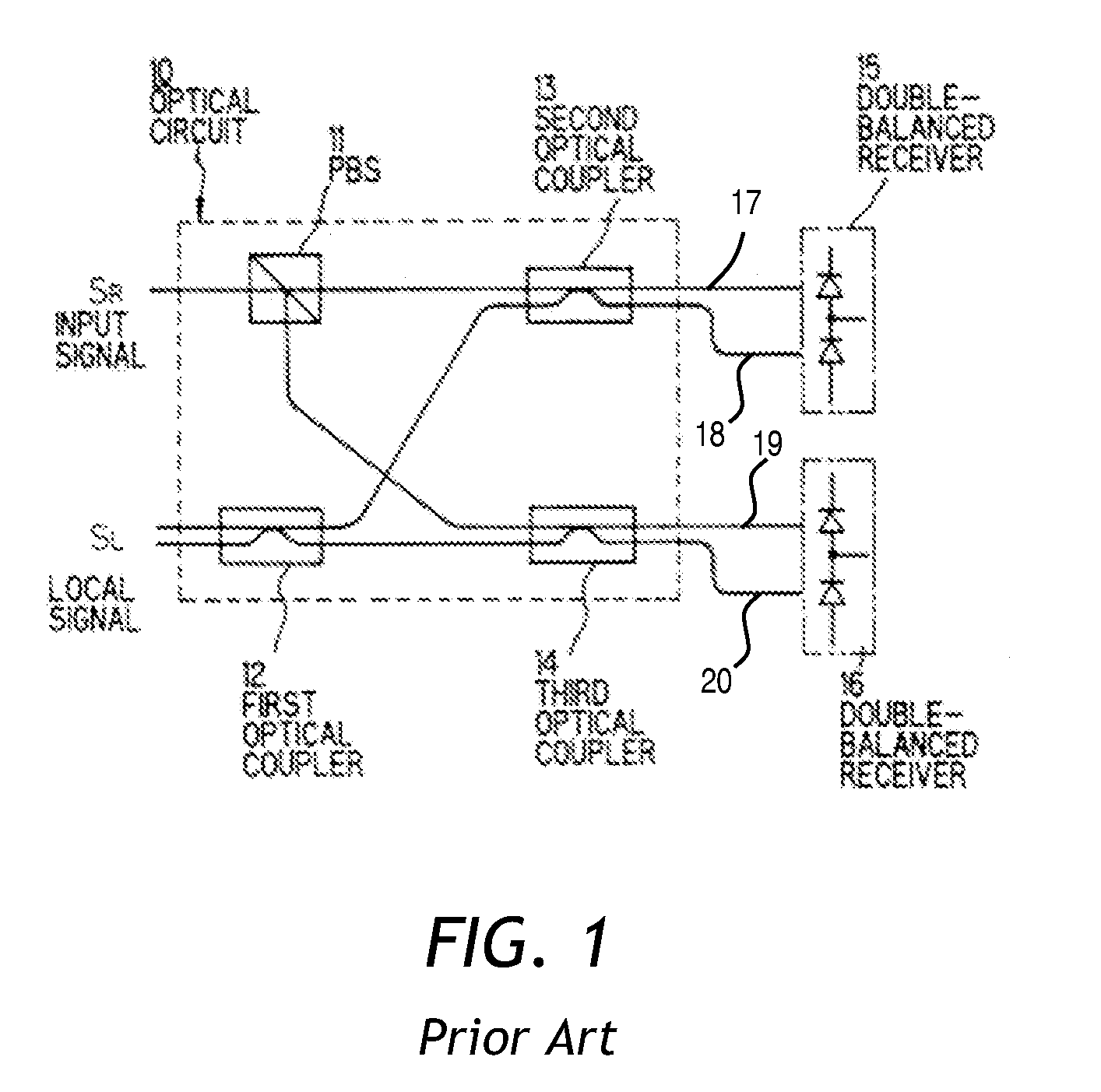
[0029]Referring to FIG. 1, a conventional optical circuit 10 of a coherent mixer is shown. The circuit 10 uses polarization diversity arrangement including a polarization beam splitter (PBS) 11 for splitting an input signal SR into two orthogonally polarized sub-signals, that is, TE- and TM-polarized sub-signals, and a first optical coupler 12 for splitting a local signal SL into two sub-signals. Further, the circuit 10 has second and third optical couplers 13 and 14 for mixing one of output signals of the PBS 11 and one of output signals of the first optical coupler 12, respectively. Output signals of the second and the third optical couplers 13 and 14 a...


PUM


Abstract

A coherent planar lightwave circuit (PLC) optical mixer chip is described comprising a matched pair of symmetrical four-coupler interferometers for in-phase and in-quadrature detection of two polarization components of light using a polarization diversity arrangement. The waveguide structure of the chip is symmetrical about two orthogonal central axes of the chip, whereby the effect of temperature gradients on the mixer is reduced. A light traveling from an input to an output of any of the two interferometers is cross-coupled by one of the two couplers it passes through, and is bar-coupled by the other of the two couplers, so as to compensate for polarization, wavelength, and manufacturing process dependence of bar-coupling with that of cross-coupling.

Description

CROSS-REFERENCE TO RELATED APPLICATIONS[0001]The present invention claims priority from U.S. application Ser. No. 61 / 059,820 filed Jun. 9, 2008, entitled “Thermally and mechanically isolated low-cost PLC Package” which is incorporated herein by reference for all purposes.TECHNICAL FIELD[0002]The present invention is related to coherent detection of an optical signal, and in particular to a planar lightwave circuit (PLC) coherent mixer device with polarization diversity.BACKGROUND OF THE INVENTION[0003]In optical communication systems, a light signal is encoded with a binary stream of data at a transmitter location and is sent towards a receiver location where it can be decoded, so as to re-create the stream of data at the receiver location. The most direct method of encoding of a light signal is to set an optical power level of the signal in dependence upon the information bit being transmitted. For example, a light source can be turned on when a “one” is being transmitted, and turn...

Claims


Application Information

Patent Timeline
Patent Type & Authority Applications(United States)
IPC IPC(8): G02B6/00G02B6/26G02B6/42G01B9/02
CPCG02B6/125G02B6/2713G02B2006/12159G02B2006/12147G02B6/2793
Inventor CHAPMAN, DAVID J.DOUGHERTY, DAVID J.
Owner LUMENTUM OPERATIONS LLC
Why Eureka
Try Eureka