Magnetic recording medium, magnetic recording medium manufacturing method, and magnetic disk

a technology of magnetic recording medium and manufacturing method, which is applied in the direction of recording information storage, instruments, coatings, etc., can solve the problems of large ratio of depth to width (aspect ratio), difficult to accurately form the isolation region, and difficult to accurately process the isolation region. , to achieve the effect of reducing track edge noise, improving track density, and high rigidity

Active Publication Date: 2010-01-28
WESTERN DIGITAL TECH INC
View PDF15 Cites 19 Cited by
  • Summary
  • Abstract
  • Description
  • Claims
  • Application Information

AI Technical Summary

Benefits of technology

[0061]According to this first invention, for example, it is possible to reduce track edge noise to improve the track density. Further, for example, when performing magnetic recording, it is possible to block a recording magnetic field extending toward the outside of a recording region, thereby making the boundaries of the recording magnetic field sharp.
[0062]Hereinbelow, an embodiment according to this first invention will be described with reference to the drawings. FIG. 1 shows one example of a magnetic recording medium 10 according to the embodiment of this invention. FIG. 1(a) shows one example of the structure of the magnetic recording medium 10. The magnetic recording medium 10 is a perpendicular two-layer medium type magnetic disk adapted to be mounted in a perpendicular magnetic recording type HDD (hard disk drive).
[0063]In this example, the magnetic recording medium 10 comprises a substrate 12, an adhesive layer 14, a soft magnetic layer 16, an underlayer 18, a perpendicular magnetic recording layer 30, a protective layer 26, and a lubricating layer 28 in this order. The perpendicular magnetic recording layer 30 comprises a granular layer 20, a coupling control layer 22, and a continuous film layer 24.
[0064]The substrate 12 is, for example, a glass for a base. As this base glass, there can be cited,

Problems solved by technology

Therefore, for example, when forming a groove or the like as the isolation region by a mechanical method, the ratio of the depth to the width (aspect ratio) becomes so large that accurate processing of the isolation region becomes difficult.
Even in the case of forming

Method used


Image

  • Magnetic recording medium, magnetic recording medium manufacturing method, and magnetic disk
  • Magnetic recording medium, magnetic recording medium manufacturing method, and magnetic disk
  • Magnetic recording medium, magnetic recording medium manufacturing method, and magnetic disk

Examples


embodiment 1

[0236]Hereinbelow, an embodiment according to this second invention will be described with reference to the drawings.

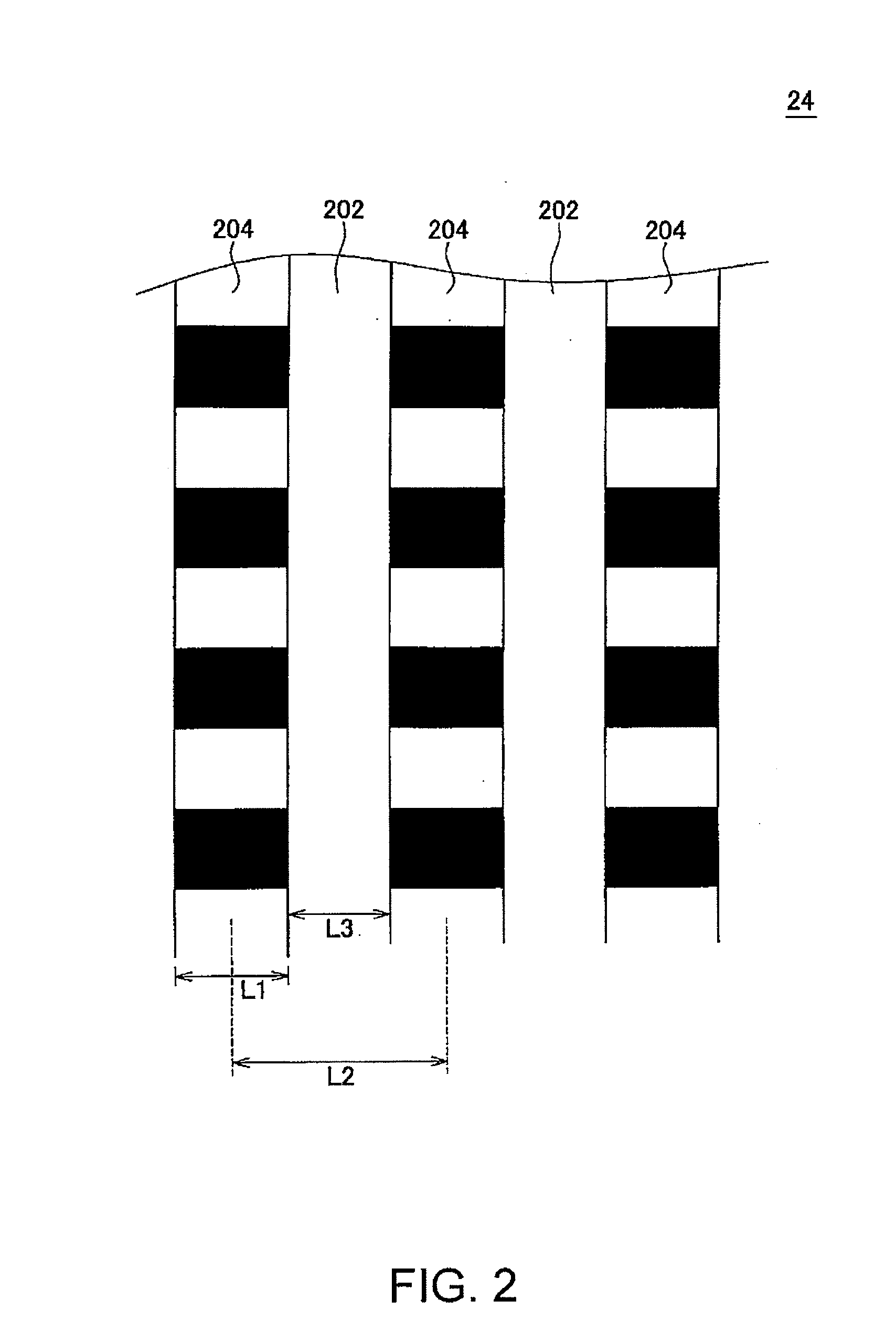
[0237]FIGS. 1, 2, 5, and 7 in the second invention are the same as FIGS. 1, 2, 5, and 7 in the first invention except that “magnetic shield portions 202” are changed to “isolation regions 202”, and therefore, a description will be given with reference to FIGS. 1, 2, 5, and 7 in the first invention. Further, data obtained in FIGS. 3 and 4 in the second invention are the same as those in FIGS. 3 and 4 in the first invention and therefore a description will be given with reference to FIGS. 3 and 4 in the first invention.

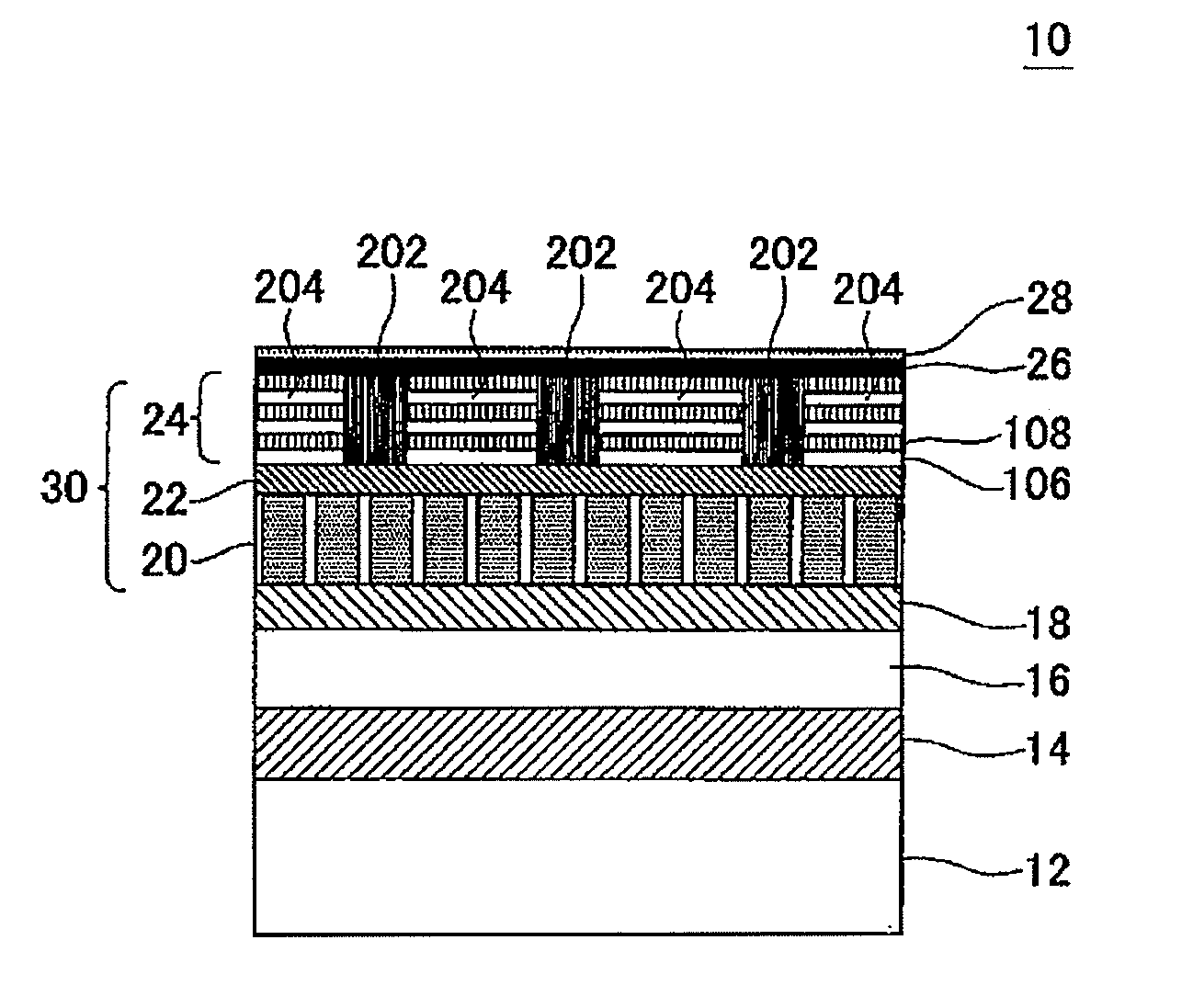
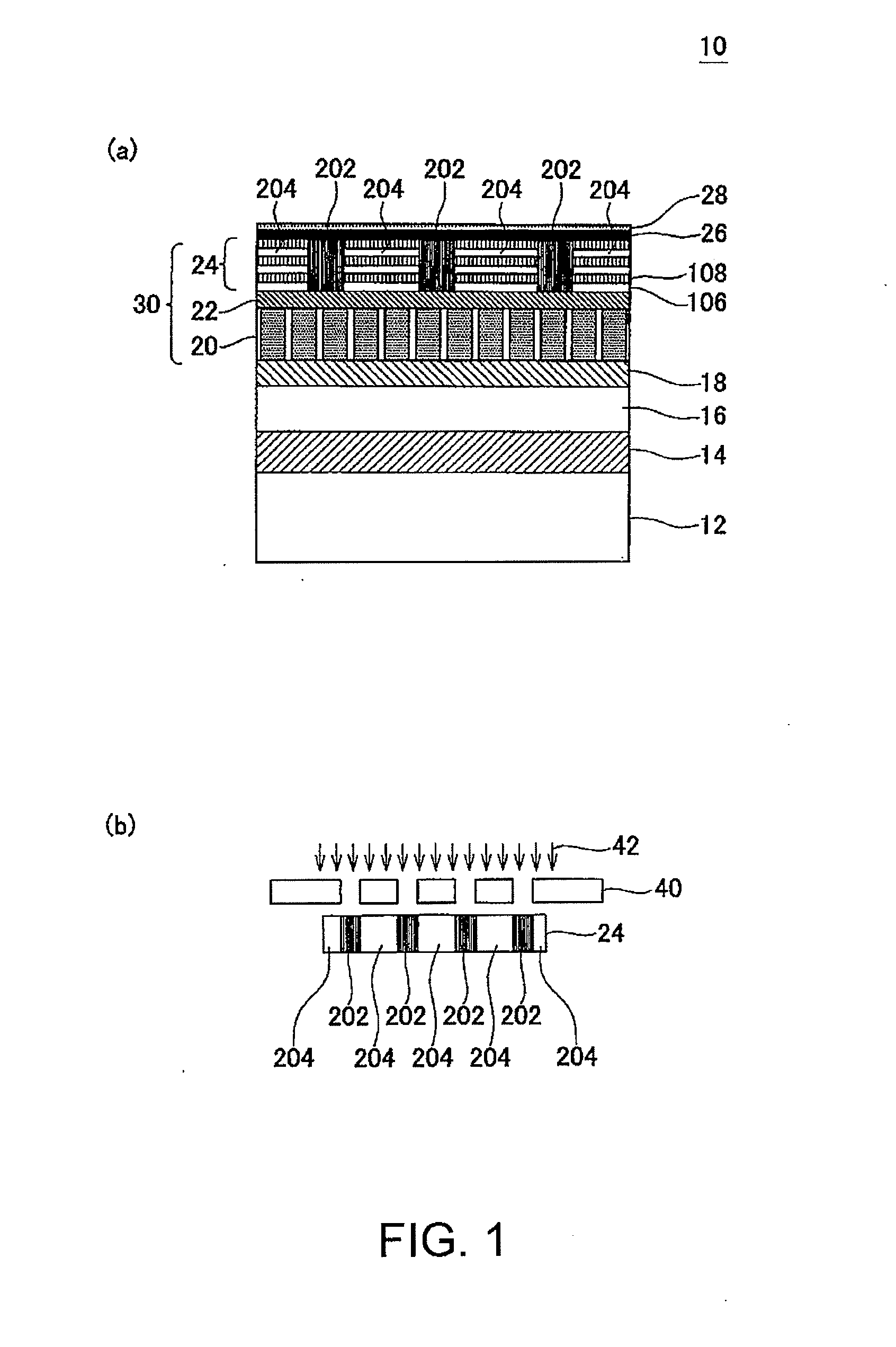
[0238]FIG. 1 shows one example of a magnetic recording medium 10 according to the embodiment of this invention. FIG. 1(a) shows one example of the structure of the magnetic recording medium 10. The magnetic recording medium 10 is a perpendicular two-layer medium type magnetic disk adapted to be mounted in a perpendicular magnetic recording type HDD (hard ...

embodiment 2

[0287]Hereinbelow, another embodiment according to this second invention will be described with reference to FIG. 7.

[0288]In this example, a magnetic recording medium 10 comprises a substrate 12, an adhesive layer 14, a soft magnetic layer 16, an underlayer 18, a perpendicular magnetic recording layer 30, a protective layer 26, and a lubricating layer 28 in this order. The perpendicular magnetic recording layer 30 comprises a granular layer 20 and a magnetically coupling layer 24′ (not continuous layers but a single layer) stacked in this order.

[0289]In this example, the substrate 12, the adhesive layer 14, the soft magnetic layer 16, the underlayer 18, the protective layer 26, and the lubricating layer 28 are the same as those in the above-mentioned embodiment 1 and thus description thereof is omitted.

[0290]In the embodiment 2, the magnetically coupling layer forms a thin film, which exhibits perpendicular magnetic anisotropy, on the magnetic recording layer with a granular structu...

example 1

[0311]Using an evacuated film forming apparatus, an adhesive layer 14 and a soft magnetic layer 16 are formed in sequence on an aluminosilicate glass substrate 12 in an Ar atmosphere by a DC magnetron sputtering method. In this event, the adhesive layer 14 is formed using a CrTi target so as to be a CrTi layer with a thickness of 10 nm. The soft magnetic layer 16 is formed using a CoTaZr target so as to be an amorphous CoTaZr layer with a total thickness of 50 nm. For controlling magnetic domains, the soft magnetic layer 16 has a two-layer structure with a Ru layer with a thickness of 0.9 nm interposed therebetween.

[0312]After forming the soft magnetic layer 16, continuously, a Ta layer (thickness 3 nm) serving as a first orientation control layer and Ru layers (thickness 20 nm) serving as a second orientation control layer and an isolation promoting layer are formed as an underlayer 18 in the Ar atmosphere by the DC magnetron sputtering method. Then, a granular layer 20 having a th...


PUM

PropertyMeasurementUnit
Magnetic fieldaaaaaaaaaa
Structureaaaaaaaaaa
Densityaaaaaaaaaa

Abstract

[PROBLEMS] To improve the track density by reducing the track edge noise and sharpening the boundaries of a recording magnetic field by blocking the recording magnetic field spreading outside the recording region in magnetic recording.
[MEANS FOR SOLVING PROBLEMS] A magnetic recording medium (10) has a substrate (12) and a perpendicular magnetic recording layer (30) formed over the substrate (12). The perpendicular magnetic recording layer (30) has a granular layer (20) in which a magnetic signal is recorded and a continuous film layer (24) magnetically coupled to the granular layer (20). The continuous film layer (24) has hard magnetic portions (204) formed in positions corresponding to the recording regions where magnetic signals are recorded in the granular layer (20) and magnetic shield portions (202) formed between the hard magnetic portions (204), each having a magnetization curve whose slope is larger than those of the hard magnetic portions in the region where the applied magnetic filed is zero when the magnetization curve is measured, and each having a residual magnetic polarization smaller than those in the hard magnetic portions.

Description

TECHNICAL FIELD [0001]This invention relates to a magnetic recording medium and a magnetic recording medium manufacturing method. Particularly, this invention relates to a perpendicular magnetic recording medium adapted to be mounted in a perpendicular magnetic recording type HDD (hard disk drive) or the like and to a manufacturing method thereof.BACKGROUND ART[0002]In recent years, the information-oriented society has continued the rapid advance and the information recording capacity exceeding 200 Gbytes has been required per 2.5-inch magnetic disk in magnetic recording apparatuses represented by HDDs (hard disk drives). In order to satisfy such a requirement in the magnetic disk, it is necessary to realize an information recording density (areal recording density) exceeding 200 Gbits per square inch (200 Gbits / inch2). Since high recording resolution can be obtained in the perpendicular magnetic recording system comprising a perpendicular two-layer medium and a single-pole head, it...

Claims


Application Information

Patent Timeline
IPC IPC(8): G11B5/667B05D5/12B05D3/00G11B5/64
CPCG11B5/855G11B5/66
Inventor SONOBE, YOSHIAKIONOUE, TAKAHIROWAGO, KOICHI
Owner WESTERN DIGITAL TECH INC
Why Eureka
Try Eureka