
Magnetoresistive Element, Magnetic Memory Cell and Magnetic Random Access Memory Using the Same

a magnetic memory cell and random access memory technology, applied in the field of tunnel magnetoresistive elements, and low-power consumption, non-volatile magnetic memory, to achieve the effect of long retention time of magnetic information and high thermal stability

Active Publication Date: 2010-02-11
TOHOKU UNIV
View PDF15 Cites 61 Cited by
  • Summary
  • Abstract
  • Description
  • Claims
  • Application Information

AI Technical Summary

Benefits of technology

[0008]It is an object of the present invention to provide a tunnel magnetoresistive element being capable of adjusting the center of such minor loop to the zero magnetic field, and having a high stability for the low-current writing and against the thermal disturbance, and to provide a nonvolatile magnetic memory using the same.
[0009]In the present invention, on a ferromagnetic free layer of the tunnel magnetoresistive element, being on the opposite side of a ferromagnetic pinned layer, an insulating layer, such as an oxide layer, and a nonmagnetic conductive layer are stacked in this order. If an MgO layer having a (100)-oriented rock salt structure is applied to the insulating layer that constitutes the tunnel barrier layer of the tunnel magnetoresistive element, and a compound ferromagnetic layer having a body-centered cubic lattice of Co or Fe containing B is applied to a ferromagnetic free layer and a ferromagnetic pinned layer, then the best effect can be obtained when the MgO layer having a (100)-oriented rock salt structure that is thinner than the insulating layer (insulating barrier layer) is used for the oxide layer and further a metal conductive layer having a body-centered cubic lattice structure of Cr or the like is used for the nonmagnetic conductive layer.
[0011]According to the present invention, a low current writing in the precisely zero magnetic field and a high thermal stability therein can be achieved, i.e., a high-output tunnel magnetoresistive element having a long retention time of the magnetic information, can be obtained. Moreover, by providing this tunnel magnetoresistive element in a magnetic memory, a nonvolatile memory can be achieved.

Problems solved by technology

However, since the magnitude of the leakage magnetic field depends on the material of the magnetic layer or the dimension of the element, the control is extremely difficult, and therefore the center of the minor loop needs to be adjusted accurately to the zero magnetic field using another method.

Method used


Image

  • Magnetoresistive Element, Magnetic Memory Cell and Magnetic Random Access Memory Using the Same
  • Magnetoresistive Element, Magnetic Memory Cell and Magnetic Random Access Memory Using the Same
  • Magnetoresistive Element, Magnetic Memory Cell and Magnetic Random Access Memory Using the Same

Examples


embodiment 1

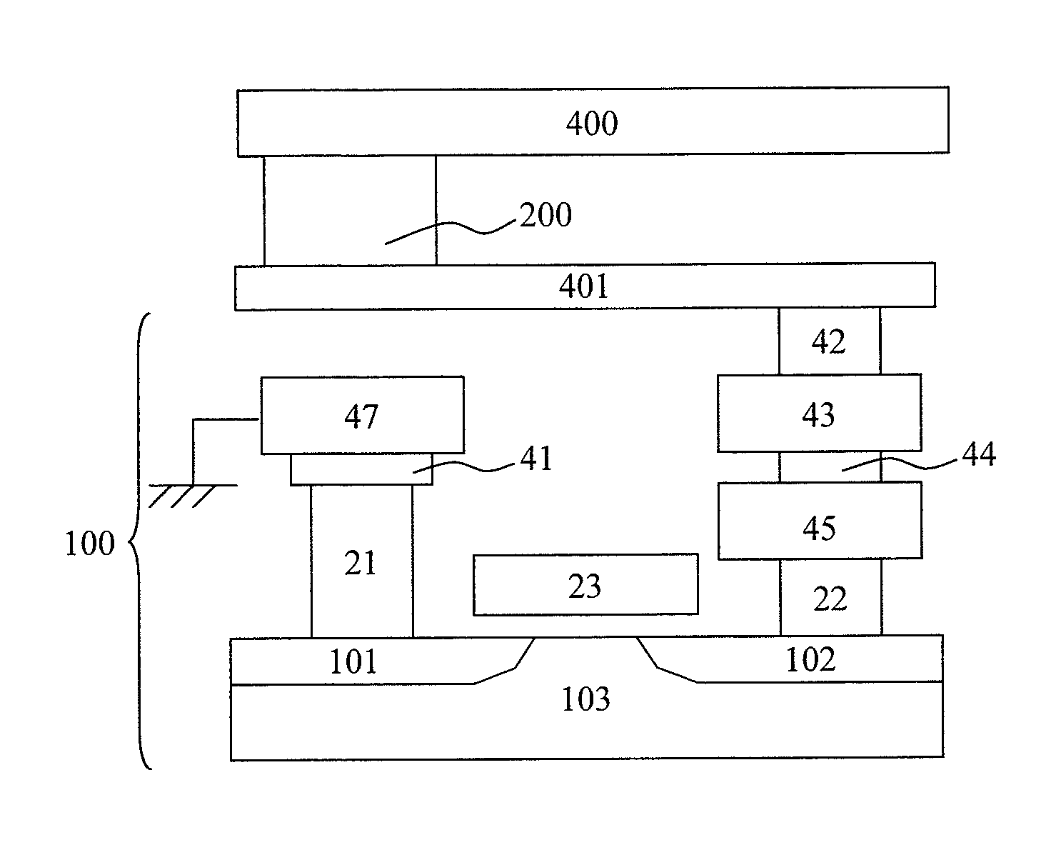
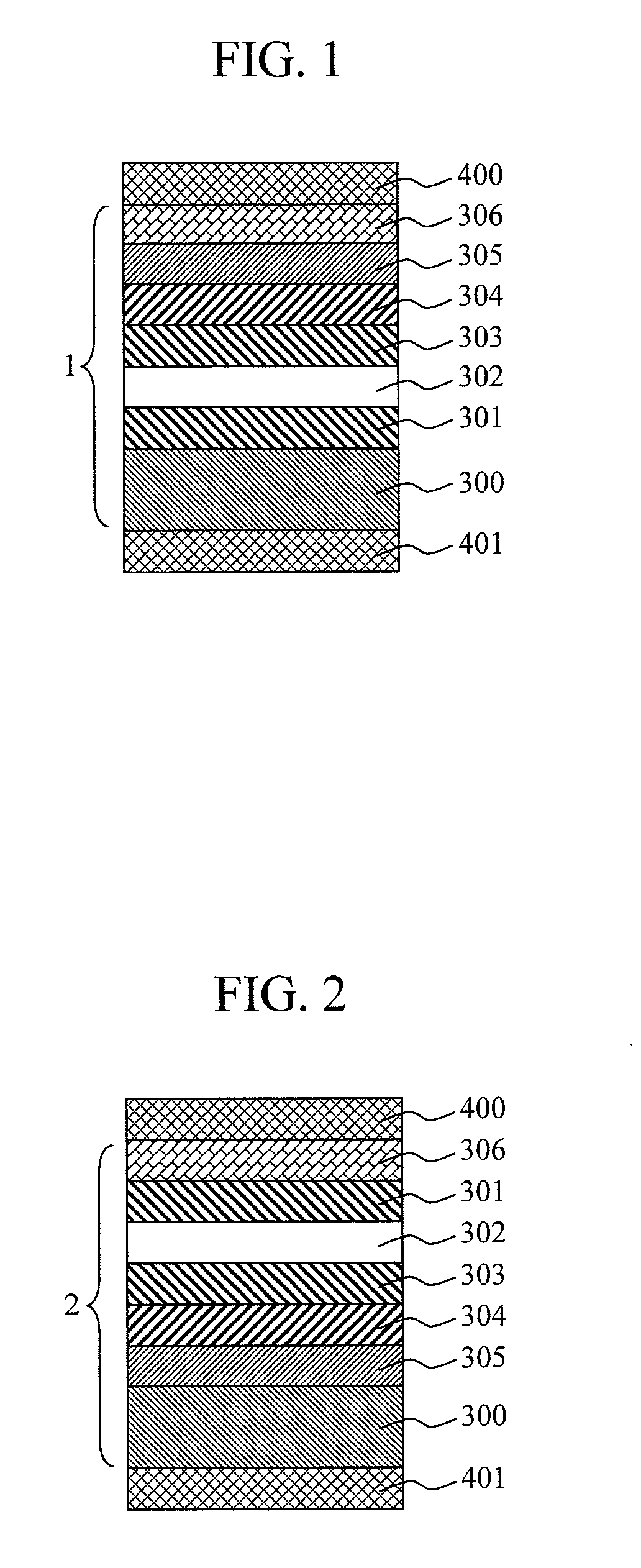
[0064]FIG. 1 is a schematic cross sectional view showing an example of a tunnel magnetoresistive element according to the present invention. The tunnel magnetoresistive element of this embodiment is manufactured using a sputtering method. Furthermore, by means of a lithography using a combination of an electron beam lithography system and a stepper, a tunnel magnetoresistive film 1 having a dimension of 100×200 nm2 is manufactured in order to implement the spin-transfer torque magnetization reversal. The tunnel magnetoresistive film 1 comprises an orientation control layer 300, a ferromagnetic pinned layer 301, an insulating barrier layer 302, a ferromagnetic free layer 303, an insulating layer 304, a nonmagnetic conductive layer 305, and a protective layer 306. Electrodes 400, 401 are respectively provided in contact with the upper and lower sides of the tunnel magnetoresistive film 1 to constitute the tunnel magnetoresistive element.

[0065]Next, a method of writing and reading info...

embodiment 2

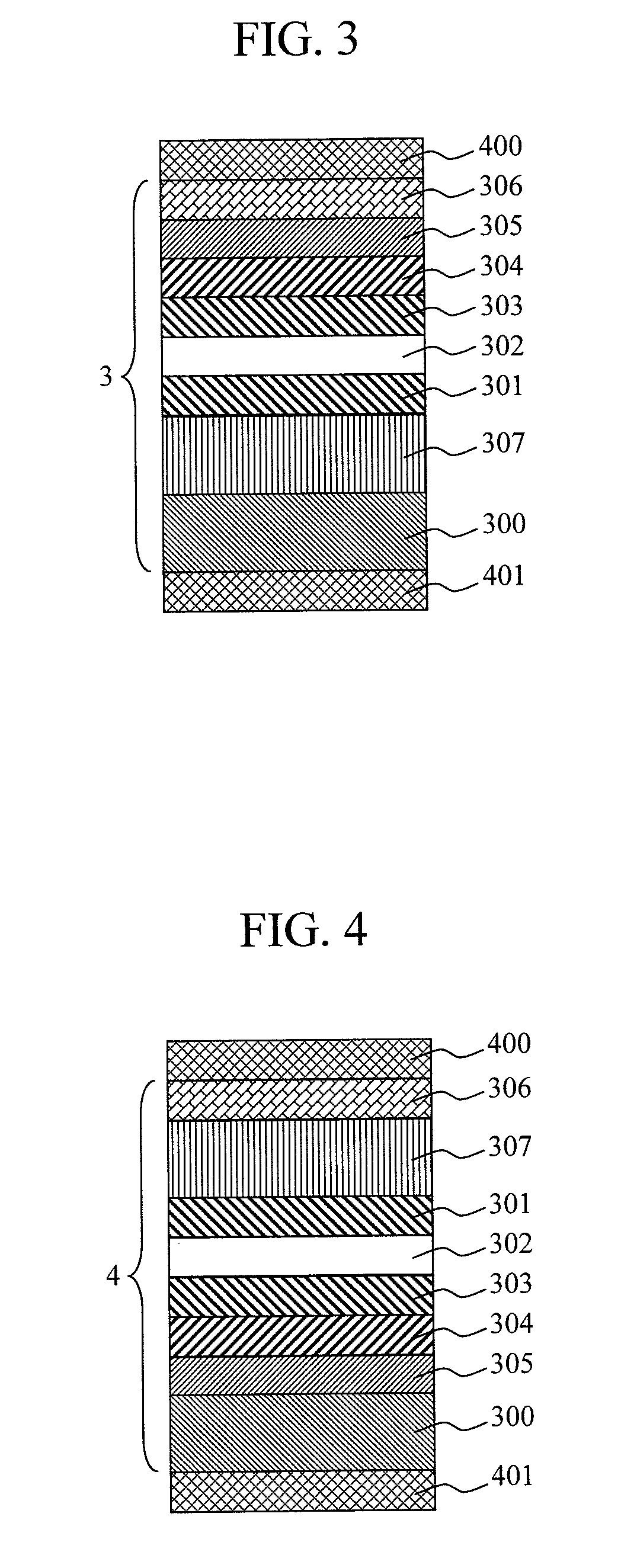
[0083]FIG. 3 and FIG. 4 are schematic cross sections showing tunnel magnetoresistive elements provided with a tunnel magnetoresistive film 3 and a tunnel magnetoresistive film 4 according to the present invention. The tunnel magnetoresistive film 3 shows a structure, in which an antiferromagnetic layer 307 is provided between the orientation control layer 300 and the ferromagnetic pinned layer 301 on the basis of the structure of the tunnel magnetoresistive film 1, and the tunnel magnetoresistive film 4 shows a structure, in which the antiferromagnetic layer 307 is provided between the ferromagnetic pinned layer 301 and the protective layer 306 on the basis of the structure of the tunnel magnetoresistive film 2, respectively. The layer structure of the tunnel magnetoresistive element of this embodiment and the material and thickness of each layer are the same as those of Embodiment 1 except the antiferromagnetic layer 307.

[0084]The antiferromagnetic layer 307 of this embodiment is u...

embodiment 3

[0086]FIG. 5 and FIG. 6 are schematic cross sections showing tunnel magnetoresistive elements provided with a tunnel magnetoresistive film 5 and a tunnel magnetoresistive film 6 according to the present invention. The tunnel magnetoresistive film 5 has a structure, in which the ferromagnetic pinned layer 301 comprises a first ferromagnetic layer 3011, a first nonmagnetic layer 3012, and a second ferromagnetic layer 3013 on the basis of the structure of the tunnel magnetoresistive film 3. On the other hand, the tunnel magnetoresistive film 6 has a structure, in which the ferromagnetic pinned layer 301 comprises the first ferromagnetic layer 3011, the first nonmagnetic layer 3012, and the second ferromagnetic layer 3013 on the basis of the structure of the tunnel magnetoresistive film 4. The layer structure of the tunnel magnetoresistive element of this embodiment and the material and thickness of each layer are the same as those of Embodiment 2 except the ferromagnetic pinned layer 3...


PUM


Abstract

Provided is a high-speed and ultra-low-power-consumption nonvolatile memory having a high temperature stability at a zero magnetic field. In a tunnel magnetoresistive film constituting a nonvolatile magnetic memory that employs a writing method using a spin-transfer torque, an insulating layer and a nonmagnetic conductive layer are stacked above a ferromagnetic free layer.

Description

CLAIM OF PRIORITY[0001]The present application claims priority from Japanese application JP 2007-32420 filed on Feb. 13, 2007, the content of which is hereby incorporated by reference into this application.BACKGROUND OF THE INVENTION[0002]1. Field of the Invention[0003]The present invention relates to a tunnel magnetoresistive element, and a low-power-consumption, nonvolatile magnetic memory provided with the same.[0004]2. Description of the Related Art[0005]As the tunnel magnetoresistive element to be employed in a highly integrated magnetic memory in the future, known are a tunnel magnetoresistive element using an oxide of Al for an insulating barrier layer (T. Miyazaki and N. Tezuka, J. Magn. Magn. Mater. 139, L231 (1995)), and a tunnel magnetoresistive element using magnesium oxide for an insulating barrier layer (S. Yuasa. et al., Nature Material 3, 868 (2004)). The latter tunnel magnetoresistive element provides a magnetoresistance ratio several times larger than that of the f...

Claims


Application Information

Patent Timeline
IPC IPC(8): G11C11/00H01L29/82
CPCG11C11/16H01L43/08H01L27/228G11C11/161G11C11/1673G11C11/1675H10B61/22H10N50/10
Inventor OHNO, HIDEOIKEDA, SHOJILEE, YOUNG MINHAYAKAWA, JUN
Owner TOHOKU UNIV
Learn More