System for simultaneous tabbing and stringing of solar cells

a solar cell and tabbing technology, applied in the field of solar cell array manufacturing, can solve the problems of poor yield and reliability of solder joints, inability to tightly pack pv cells, and large labor and capital equipment required for assembly of solder joints, so as to improve the adhesion of ribbons and reduce relative thermal expansion. , the effect of improving the quality of the soldering

Inactive Publication Date: 2010-02-18
VSERV TECH CORP
View PDF10 Cites 51 Cited by
  • Summary
  • Abstract
  • Description
  • Claims
  • Application Information

AI Technical Summary

Benefits of technology

[0005]In conventional PV cell stringing methods, a single ribbon attaches along the front surface of a first PV cell (soldered to a bus bar on the first PV cell front surface), extends past the PV cell edge, then bends down and attaches along the bottom of the neighboring cell (soldered to a bus bar on the second PV cell back surface). One aspect of the present invention includes a mono / multi crystalline silicon photovoltaic module comprising, a first photovoltaic cell (PV cell) with a top interconnect tab (ribbon) and a second photovoltaic cell with a bottom interconnect tab (ribbon). The advantage of this improved PV cell interconnection method is improved quality of the soldering of the ribbons to the PV cell bus bars since this soldering operation is done separately from the stringing operation which interconnects neighboring PV cells. Neighboring cells are instead interconnected by the separate soldering step which attaches a first ribbon from a first PV cell to a second ribbon from the neighboring second PV cell—this soldering operation may be accomplished with a soldering head separate from those used to attach the front and back surface ribbons to the bus bars on the PV cells.
[0006]Another aspect of the present invention is a system for the tabbing of PV cells—this is the process step in which ribbons are attached to the front and back surfaces (onto bus bars) of a single wafer. The front side ribbons (typically two or three) are arranged to overhang one edge of the wafer from the front surface of the wafer, and the back side ribbons (the same number as for the front side ribbons) are arranged to overhang the opposite edge of the wafer. Soldering heads are pressed against the front and back surfaces simultaneously (or nearly so) to rapidly head the ribbon to enable low-stress solder bonds between the ribbons and the bus bars on the wafer. Further ribbon-to-wafer stress reduction may be accomplished by means of a sequencing method in which only selected portions of the ribbon are heated at any one time, and the spatial relationships of the heated portions are selected to reduce the relative thermal expansion between the ribbons and the wafer, thereby enhancing ribbon-to-wafer adhesion.
[0007]A still further aspect of the present invention is a method for stringing PV cells together to form “strings” of PV cells wired in series, typically with 10 to 12 cells each. When a string is completed, it is transferred to a secondary belt which supports the string prior to the loading of the string into the solar array being assembled. This method improves overall system throughput since the next string can be started before the just-completed string has been transferred into the solar array.
[0008]Another aspect of the present invention is the use of a rotary turntable including multiple bins for PV cells: For example, a system with three such bins may include a first bin from which PV cells (wafers) are loaded into the tabbing subsystem, a second bin in which PV cells are loaded by the system operator or an external robotic apparatus, and a third bin for storage of rejected PV cells. When all the PV cells have been loaded into the tabbing system from the first bin, the turntable rotates to position the second bin for loading PV cells into the tabbing subsystem while new PV cells are being loaded into the first bin. This aspect of the present invention improves throughput since the tabber stringer system experiences minimal idle time waiting for PV cells to be loaded.

Problems solved by technology

One drawback with the “tabbing and stringing” method is the poor yield and reliability of the solder joints that fail due to thermal coefficient of expansion mismatches and soldering defects.
These solder joints require significant labor and capital equipment to assemble and do not allow the PV cells to be closely packed since gaps must be left between adjacent PV cells in the solar array to allow space for the tabbed electrical interconnects between adjacent PV cells.

Method used


Image

  • System for simultaneous tabbing and stringing of solar cells
  • System for simultaneous tabbing and stringing of solar cells
  • System for simultaneous tabbing and stringing of solar cells

Examples


Embodiment Construction

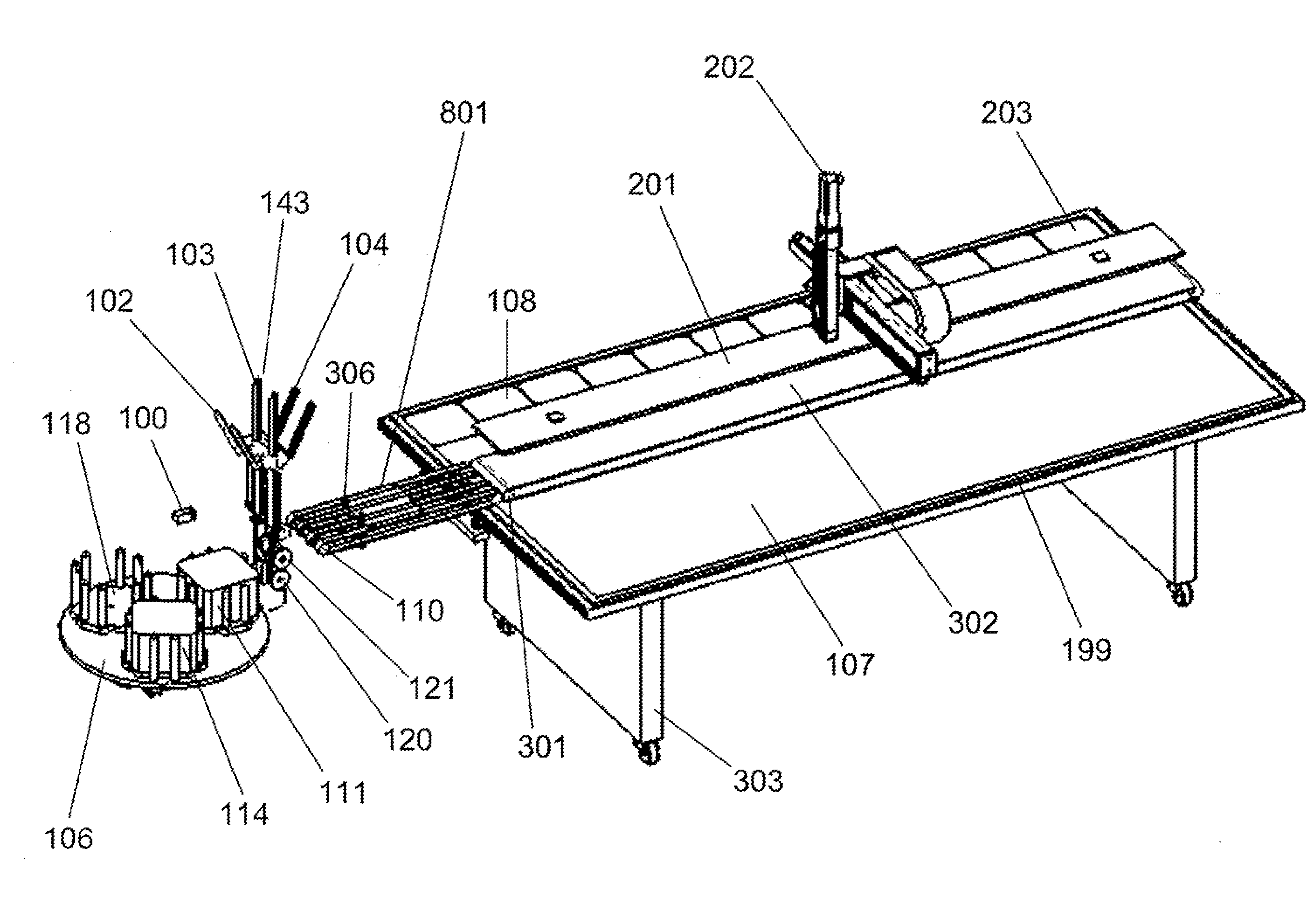
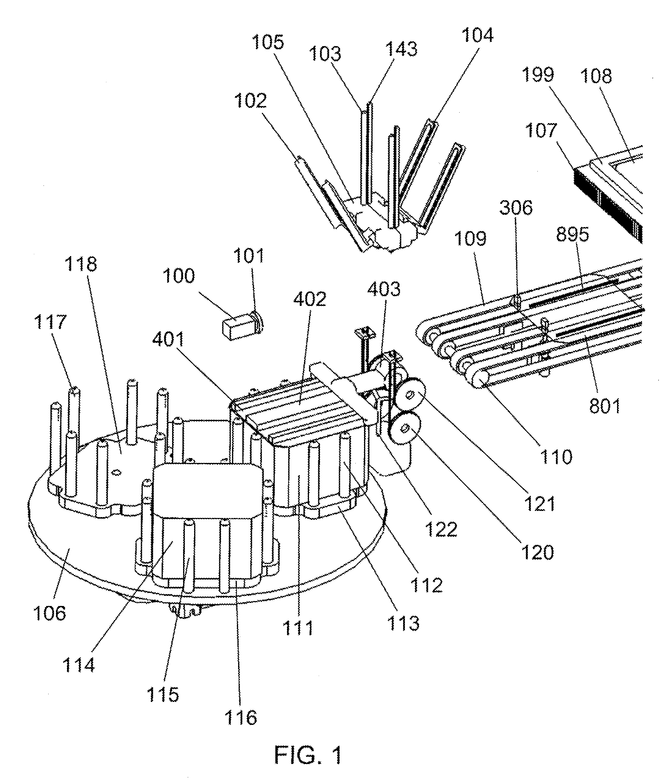
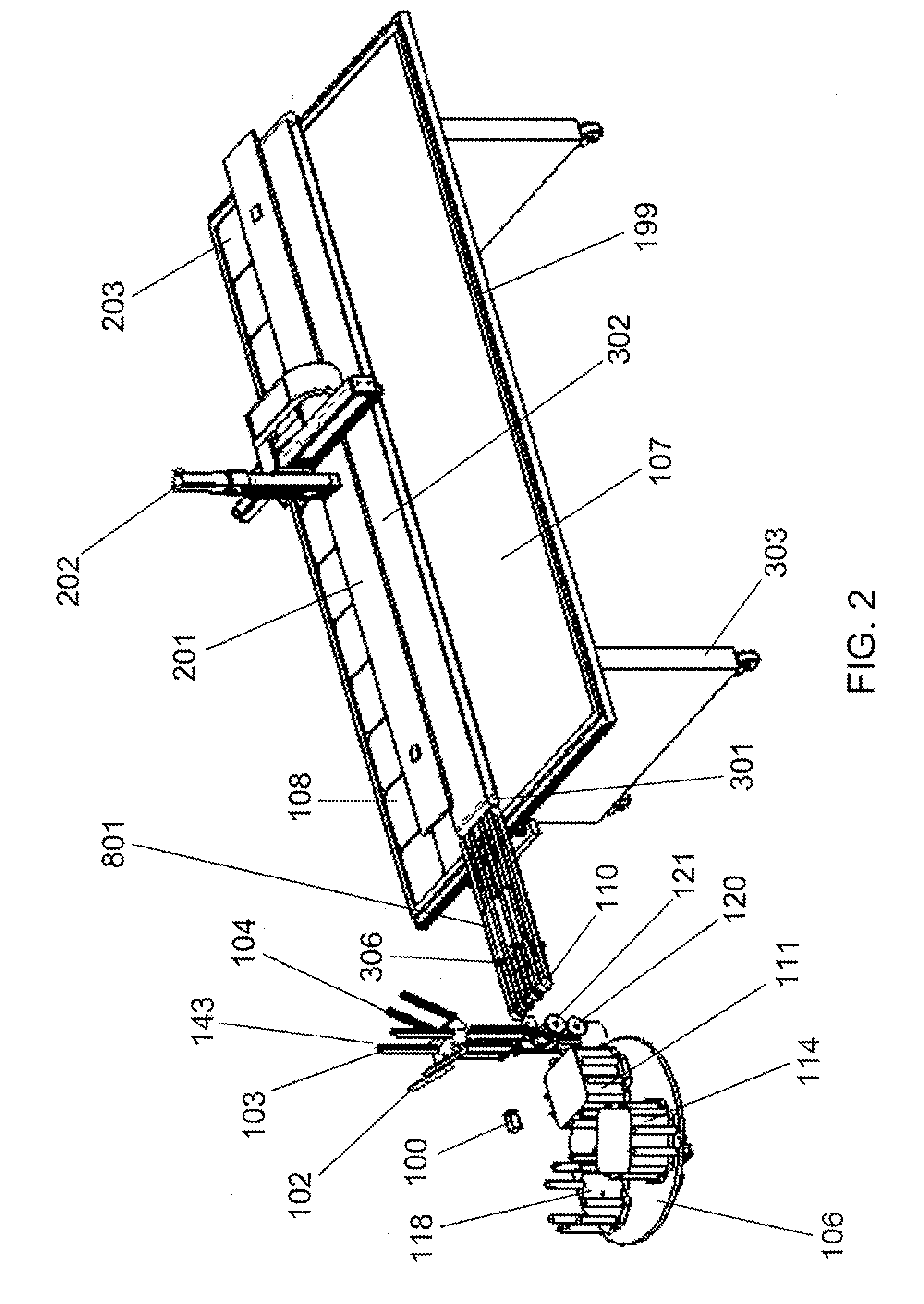
[0034]Described herein is a system configured for the combined tabbing and stringing of photovoltaic solar cells (PV cells or wafers) together, and the subsequent assembly of strings of PV cells into a solar cell array. The system includes the following main subsystems:[0035]1) Wafer bin turntable—this turntable contains multiple (e.g., three) bins: for example, one bin containing wafers being individually loaded into the tabbing subsystem, a second bin being loaded with wafers, and a third bin for rejected wafers. In other embodiments, more than three bins may be used. For example, alternating pairs of wafer containing bins may be used to provide multiple operational positions, as will be apparent from the discussion below. This may be especially useful where tabbing and stringing operations are performed by pairs of assemblies (e.g., two such assemblies, four such assemblies, etc.).[0036]2) Vacuum arm wafer transfer subsystem—transfers wafers between the bins, tabbing subsystem an...


PUM

PropertyMeasurementUnit
angleaaaaaaaaaa
distanceaaaaaaaaaa
clamping forceaaaaaaaaaa

Abstract

A method for stringing photovoltaic (PV) cells together and a system for the combined tabbing and stringing of photovoltaic (PV) cells for assembly into solar cell arrays. Multiple ribbons are first soldered simultaneously (or nearly so) to the front and back surfaces of individual PV cells (tabbing). After tabbing, PV cells are then loaded into a stringer subsystem which solders the front side ribbons of a first PV cell to the back side ribbons of the neighboring PV cell to form strings of PV cells wired in series. The tabber stringer system then loads completed strings into a frame containing a solar cell array being manufactured. The dual-ribbon method of PV cell interconnection reduces the electrical resistance between the cells in a string, thereby raising the solar cell array output power.

Description

RELATED APPLICATIONS[0001]This application is a NONPROVISIONAL and claims the priority benefit of U.S. Provisional Patent Application 61 / 058,446, filed Jun. 3, 2008, which is incorporated herein by reference.FIELD OF THE INVENTION[0002]This invention relates to the manufacture of solar cell arrays, and, in particular, to photovoltaic device interconnection methods and related apparatus for solar cell manufacturing.BACKGROUND[0003]Traditionally, photovoltaic (PV) cells are interconnected using a “tabbing and stringing” technique of soldering two or three conductive ribbons to the front surface of a first solar cell and to the back surface of an adjacent cell. Typically, N (where N could be ten or twelve) PV cells are interconnected in this manner across one dimension of a solar array being manufactured. The process of attaching the ribbons to the PV cells is called “tabbing” and the process of connecting multiple PV cells together is called “stringing”. A typical solar array might ha...

Claims


Application Information

Patent Timeline
Patent Type & Authority Applications(United States)
IPC IPC(8): H01L31/042H01L31/18
CPCH01L31/188Y10T29/49355Y02E10/50
Inventor EREZ, SHMUELSCHOCK, GERALDCHIDAMBARAM, MAHENDRAN
Owner VSERV TECH CORP
Why Eureka
Try Eureka