Fine positioning system using an inertial motor based on a mechanical amplifier

a mechanical amplifier and positioning system technology, applied in piezoelectric/electrostrictive/magnetostrictive devices, basic electric elements, electric devices, etc., can solve problems such as system malfunction, loss of coherence, and solder and electrode temperature rise of piezoelectric elements, so as to improve the performance and dependability of piezoactive inertial motors

Active Publication Date: 2010-02-18
CEDRAT TECH
View PDF3 Cites 28 Cited by
  • Summary
  • Abstract
  • Description
  • Claims
  • Application Information

AI Technical Summary

Benefits of technology

[0020]The object of the invention is to remedy these shortcomings and, more particu

Problems solved by technology

This results in an electric current of intensity I=C.V/t1=15 A. This high current, due to the short switching time t1 necessary for fast deformations, solicits the electronics and causes temperature rises in the solders and the electrodes of the piezoelectric elements.
It is a source of malfunctioning for the system.
Such sticking is subject to ageing leading in the longer term to a loss of coherence between the piezoelectric element and the mass elements m and M. On account of these stickings, this mechanical structure comprises sources of malfunctions.
This leads to the size of the steps and incidentally the speed being limited and therefore to the performances of the motor being reduced, or in the opposite case in the lifetime of the mechanism being reduced.
These vibratio

Method used


Image

  • Fine positioning system using an inertial motor based on a mechanical amplifier
  • Fine positioning system using an inertial motor based on a mechanical amplifier
  • Fine positioning system using an inertial motor based on a mechanical amplifier

Examples


Embodiment Construction

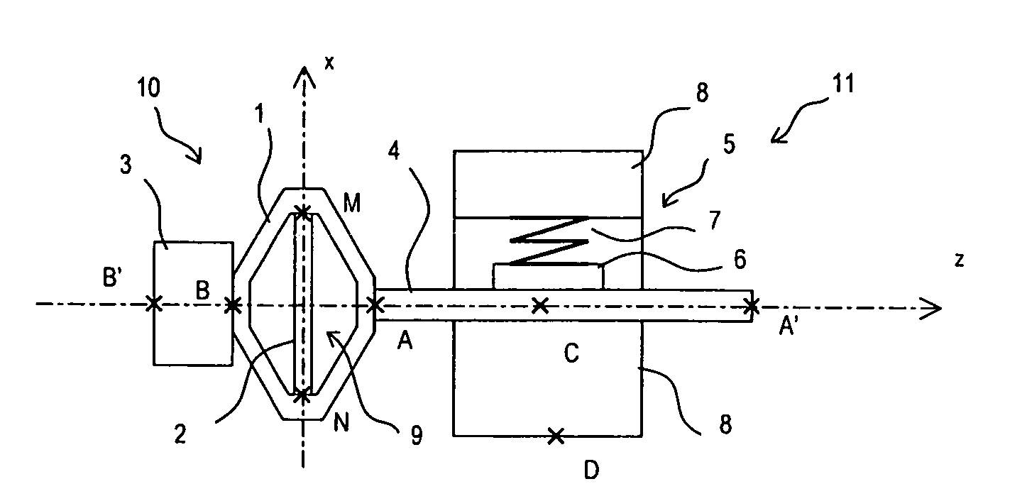
[0043]With reference to FIG. 1, the inertial motor comprises a first inertial sub-assembly 10 formed by a mechanical amplifier 1, a piezoactive element 2 and a countermass 3, and a second relative drive sub-assembly 11 comprising in particular a clamp 5 and a clamped member in the form of a shaft 4 oriented along the z-axis. Clamp 5 is formed by a pad 6 in sliding contact with shaft 4 towards point C and by a flexible preloading system 7 secured to the frame 8. System 7 is designed to produce a static force F perpendicular to the z-axis. If point D is fixed, the load to be driven in relative movement can be fixed either towards point A or in its extension A′ onto shaft 4 or towards point B or onto countermass towards B′. If point B is fixed, the load to be driven can be fixed towards point D.

[0044]Clamp 5 and clamped member 4 can be replaced by any other type of drive member and driven member.

[0045]Mechanical amplifier 1 presents an actuating point A and an inertia point B. Mechanic...


PUM


Abstract

The invention relates to a fine positioning system using an inertial motor based on a mechanical amplifier that comprises a first amplified inertial sub-assembly including a mechanical amplifier, a piezoactive member and a countermass. A second relative drive sub-assembly includes a clamp and a clamped member attached to the first amplified inertial sub-assembly. Asymmetric excitation cycles of the first inertial sub-assembly generate impact forces and movements amplified in a driving direction (z), thus resulting in sliding and adhesion successions of the clamped member in the clamp in order to generate a relative translation movements of the points A and B relative to the point D. The mechanical amplifier increases the step size and reduces the supply inrush currents. Fine and dynamic positioning of the point B relative to the point D can be achieved with augmented strokes using the amplifier.

Description

BACKGROUND OF THE INVENTION[0001]The invention relates to precise positioning systems comprising:[0002]a first inertial sub-assembly including at least one piezoactive element and at least one inertia point, and able to produce impact forces and movements at an actuating point in an actuating direction,[0003]a second relative drive sub-assembly including at least one drive member and one driven member, one of the two members being fixed to the first inertial sub-assembly via the actuating point,[0004]an electronic circuit for supplying each piezoactive element of the first inertial sub-assembly according to predefined excitation cycles.STATE OF THE ART[0005]Piezoelectric inertia motors are used in precision linear or rotary micro-motorization applications, for example in optics for focusing functions or in microscopy for micro-positioning of samples.[0006]The concept of the piezoelectric inertial motor is described for example in Patent EP 0292989 by T. Higuchi. A piezoelectric elem...

Claims


Application Information

Patent Timeline
IPC IPC(8): H02N2/04H02N2/12
CPCH02N2/025H02N2/108H02N2/101H02N2/043
Inventor CLAEYSSEN, FRANKBARILLOT, FRANCOIS
Owner CEDRAT TECH
Why Eureka
Try Eureka