
Fused silica glass and process for producing the same

a technology of fused silica glass and silica material, which is applied in glass tempering apparatus, glass making apparatus, manufacturing tools, etc., can solve the problems of contaminated silicon wafers in furnace tubes, undetectable avoidance elements in conventional fused silica glass made from natural silica materials, and contaminated simiconductor, etc., to achieve high purity, good high-temperature viscosity, and high transparency

Active Publication Date: 2010-02-18
TOSOH CORP +1
View PDF11 Cites 23 Cited by
  • Summary
  • Abstract
  • Description
  • Claims
  • Application Information

AI Technical Summary

Benefits of technology

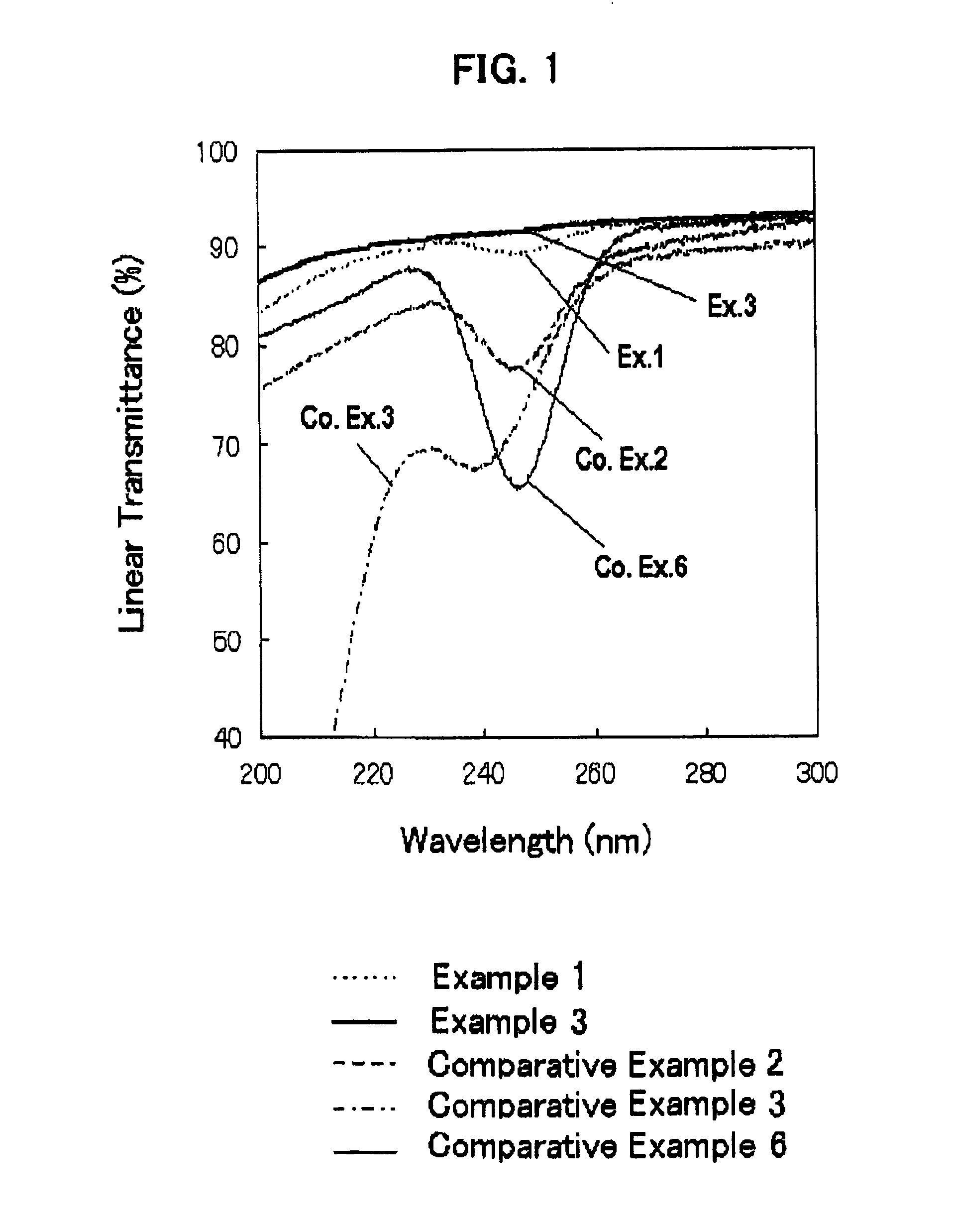
[0024]The fused silica glass of the present invention does not exhibit or exhibits only to a minimized extent a specific absorption in the wavelength region spanning from ultraviolet ray, through visible ray to infrared ray. Therefore, the fused silica glass is suitable for various optical goods for which a high transparency is required, especially useful for viewports, for example, for detecting the end point of etching. Further, the fused silica glass of the present invention has a high purity and a good high-temperature viscosity and exhibiting a reduced diffusion rate of copper ion and other metal impurities. Therefore, the fused silica glass is suitable for a member of a semiconductor-production apparatus, such as furnace material and jig, which are used for heat-treating or producing a semiconductor; a jig for a MEMS production apparatus; a lens and a lamp for ultraviolet ray; and a glass substrate for liquid crystal display.
[0025]The fused silica glass having the above-mentioned characteristics can be industrially advantageously produced by the process according to the present invention.

Problems solved by technology

In recent years, a problem arises at a step of heat-treating a semiconductor such that the semiconductor is contaminated with copper.
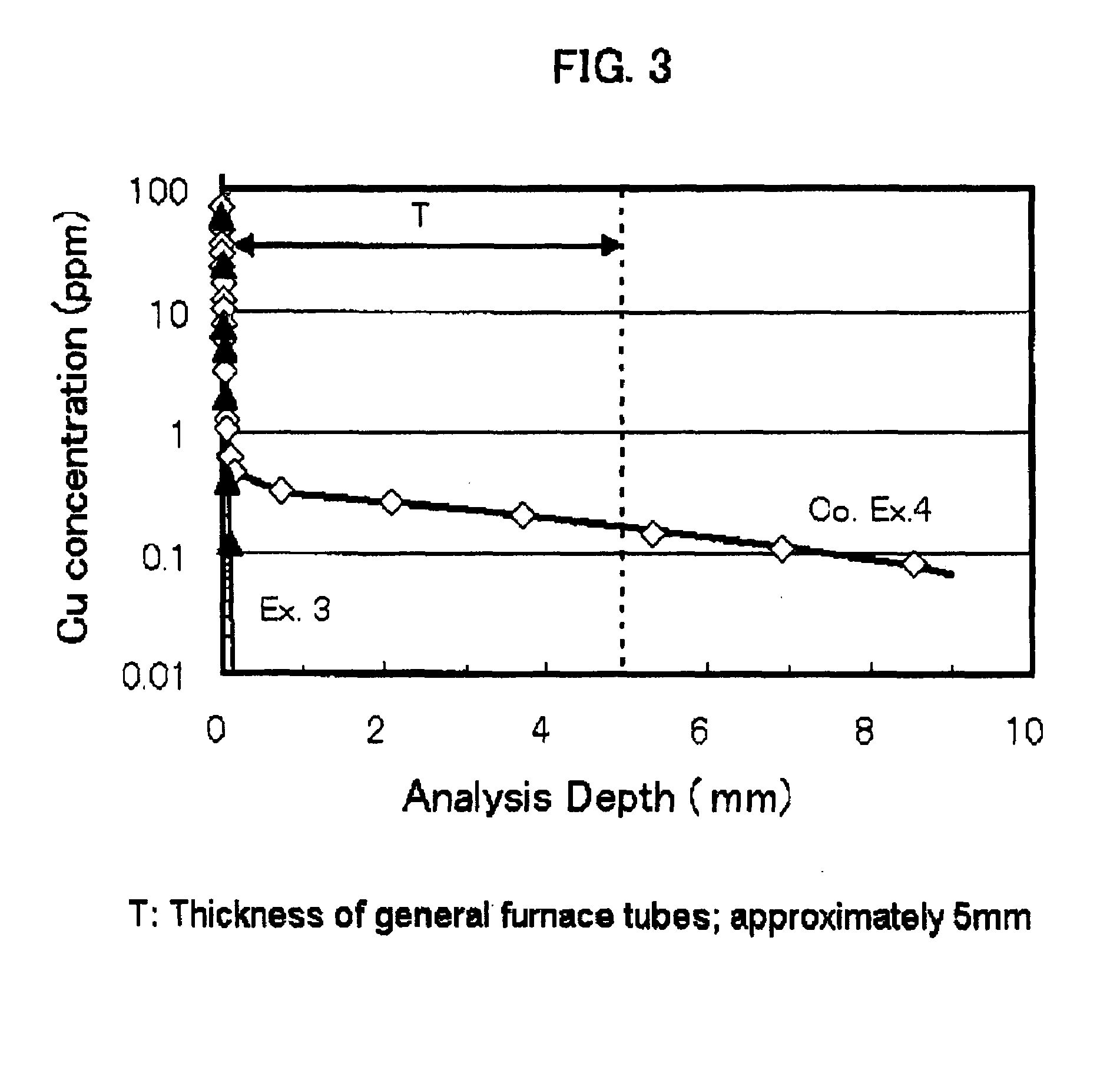
This is because copper generated by a heater outside a heat-treating silica tube (i.e., furnace tube) diffuses through the wall of furnace tube and thus a silicon wafer placed in the furnace tube is contaminated with copper.
However, the conventional fused silica glass made from a natural silica material undesirably contains avoidance elements for the production of a semiconductor, such as, for example, Li, K, Na and Ca in an amount of approximately 0.1 to 0.5 ppm.
Therefore, the conventional fused silica glass cannot be used in a field where a high purity is required, fit example, at a step of annealing a silicon wafer at a high-temperature.
Further, the conventional fused silica glass exhibits an absorption band for ultraviolet rays with a wavelength of 200 nm to 240 nm, and hence, it cannot advantageously be used as optical goods for ultraviolet rays, such as for example a viewport for end point detection.
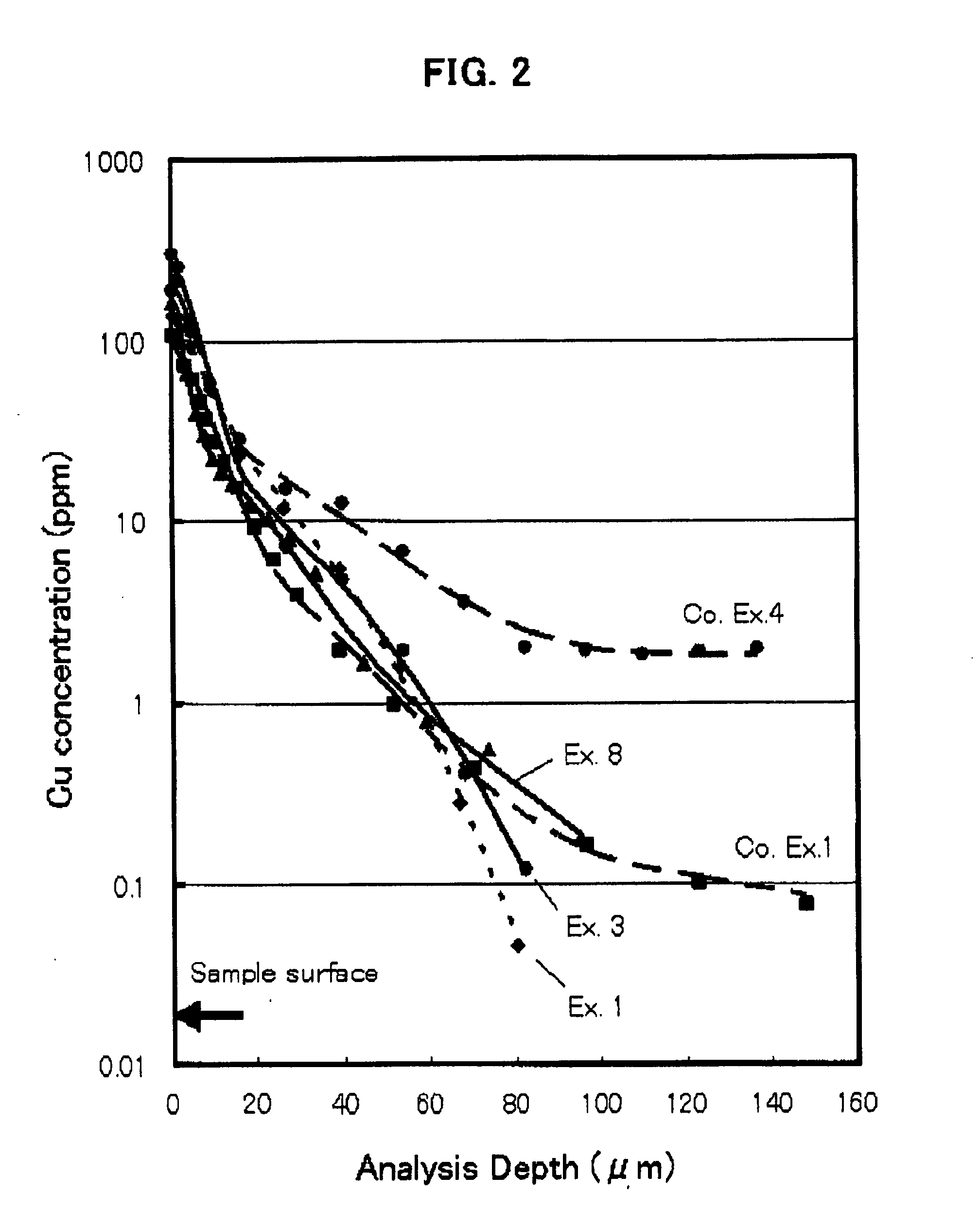
Further the conventional fused silica glass has another problem such that the diffusion rate of copper and other metal impurities is very high.
The residual OH group in the silica glass tends to cause problems such that light absorption occurs in the infrared region, the high-temperature viscosity is reduced, and diffusion of copper and other metal impurities is enhanced.
However, the proposal described in JP-A H8-119664 still has problems in that the metal impurities cannot be reduced to the desired extent, therefore, a further reduction of residual impurities is desired.
However, these production processes are complicated and the synthetic silica glass is very expensive.
Further, the process described in JP-A H3-83833 does not have a step of reducing the residual OH group, and therefore, the synthetic silica glass made by this process tends to exhibit optical absorption in the infrared ray region, reduce the high-temperature viscosity, and undesirably enhance the diffusion of copper and other metal impurities.

Method used


Image

  • Fused silica glass and process for producing the same
  • Fused silica glass and process for producing the same
  • Fused silica glass and process for producing the same

Examples


example 1

[0083]A high-purity amorphous synthetic silica powder having a particle diameter of approximately 200 μm, a OH group content of 40 ppm, and a metal impurity content such that each of Li, Na, K, Mg, Ca and Cu was not larger than 0.01 ppm, was mixed with 0.1% by weight of a crystobalite powder. The mixed powder was sintered at 1500° C. for 60 hours to give a crystobalite powder having a crystallization degree of approximately 100%.

[0084]The thus-obtained crystobalite powder was fused by a plasma arc at an input power of 590 A / 160 V and a raw material feed rate of 4.5 kg / hr in an argon atmosphere to give a glass ingot. The glass ingot was subjected to a HIP treatment, and then an annealing treatment to remove stress.

[0085]The thus-obtained fused silica glass had a metal impurity content and a OH group content, as shown in Table 1, below. The fused silica glass had an internal transmittance of ultraviolet ray with a wavelength of 245 nm, and a viscosity coefficient at 1215° C., as shown...

example 2

[0087]Substantially the same procedures as adopted in Example 1, fused silica glass was made wherein an electric fusion method was adopted instead of the plasma arc fusion method for fusing the sintered crystbalitized powder, and the fusion was conducted at 1800° C. for 1 hour in N2 atmosphere. All other conditions and procedures remained the same.

[0088]The impurity contents, internal transmittance and viscosity coefficient of the fused silica glass are shown in Tables 1 and 2. Thus the fused silica glass of Example 2 did not exhibit a specific absorption in the region spanning from ultraviolet ray to infrared ray, and had a high purity and a high viscosity.

example 3

[0089]Substantially the same procedures as adopted in Example 1, fused silica glass was made, wherein the same high-purity amorphous synthetic silica powder as used in Example 1 was mixed with an alumina powder in an amount of 1 ppm as Al metal, and the mixed powder was sintered under the same conditions as in Example 1 to give a crystobalite powder with a crystallization degree of approximately 100%, and the fused silica glass was made therefrom. All other conditions and procedures remained the same.

[0090]The impurity contents, internal transmittance and viscosity coefficient of the fused silica glass are shown in Tables 1 and 2. Thus the fused silica glass of Example 3 did not exhibit a specific absorption in the region spanning from ultraviolet ray to infrared ray, and had a high purity and a high viscosity.

[0091]The distribution of the copper ion concentration as measured when the heat-treatment was conducted at 1050° C. for 24 hours in the air using CuO as diffusion source is s...


PUM

PropertyMeasurementUnit
thicknessaaaaaaaaaa
thicknessaaaaaaaaaa
transmittanceaaaaaaaaaa

Abstract

Fused silica glass having an internal transmittance of UV with 245 nm wavelength, being at least 95% at 10 mm thickness, a OH content of not larger than 5 ppm, and a content of Li, Na, K, Mg, Ca and Cu each being smaller than 0.1 ppm. Preferably the glass has a viscosity coefficient at 1215° C. of at least 1011.5 Pa·s; and a Cu ion diffusion coefficient of not larger than 1×10⁻¹⁰ cm2 / sec in a depth range of greater than 20 μm up to 100 μm, from the surface, when leaving to stand at 1050° C. in air for 24 hours. The glass is made by crystobalitizing powdery silica raw material; then, fusing the crystobalitized silica material in a non-reducing atmosphere. The glass exhibits a high transmittance of ultraviolet, visible and infrared rays, has high purity and heat resistance, and exhibits a reduced diffusion rate of metal impurities, therefore, it is suitable for various optical goods, semiconductor-production apparatus members, and liquid crystal display production apparatus members.

Description

TECHNICAL FIELD[0001]This invention relates to fused silica glass exhibiting a high transmittance of ultraviolet ray, visible ray and infrared ray, having a high purity and a high heat resistance, and exhibiting a reduced diffusion rate of metal impurities such as copper; and a process for producing the same.[0002]The silica glass according to the present invention can be used as, for example, various optical goods, a semiconductor-producing member, a liquid crystal-producing member, a MEMS (Micro Electro Mechanical System)-producing member, and a glass substrate for liquid crystal display. The silica glass is especially suitable for use as a furnace tube used in a semiconductor-heat treating step or a CVD production process.BACKGROUND ART[0003]For use as, for example, various optical goods, a semiconductor-producing member, a liquid crystal-producing member, a MEMS-producing member, and a glass substrate for liquid crystal display, silica glass exhibiting a high transmittance of ul...

Claims


Application Information

Patent Timeline
Patent Type & Authority Applications(United States)
IPC IPC(8): C03C3/04C03C10/00
CPCC03B19/066C03B20/00C03B2201/03C03B2201/04C03C2201/54C03C4/0085C03C4/10C03C2201/23C03C2201/50C03C3/06Y02P40/57C03C4/00
Inventor ARAI, KAZUYOSHITAKAHATA, TSUTOMUHASIMOTO, SHINKICHIUCHIDA, MASAHITOYAMADA, NOBUSUKEHARADA, YOSHINORIHORIKOSHI, HIDEHARU
Owner TOSOH CORP
Learn More