System and method for energy production from sludge

a technology of energy production system and wastewater sludge, which is applied in the direction of drying machines, machines/engines, borehole/well accessories, etc., can solve the problem that traditional disposal methods are no longer attractiv

Inactive Publication Date: 2010-02-25
BOARD OF RGT NEVADA SYST OF HIGHER EDUCATION ON BEHALF OF THE UNIV OF NEVADA RENO
View PDF34 Cites 17 Cited by
  • Summary
  • Abstract
  • Description
  • Claims
  • Application Information

AI Technical Summary

Benefits of technology

[0016]The system can include additional components. For example, the system can include an anaerobic digester. The digester includes a gas outlet that is attached to a combustion unit. The combustio

Problems solved by technology

Because of the reduced availability of land, the increased public concerns over food chain safety, EPA beneficia

Method used


Image

  • System and method for energy production from sludge
  • System and method for energy production from sludge
  • System and method for energy production from sludge

Examples


example 1

Determination of Sludge Properties and Fluidized Bed Dryer Design

[0101]Materials and Methods

[0102]Equilibrium Moisture Content

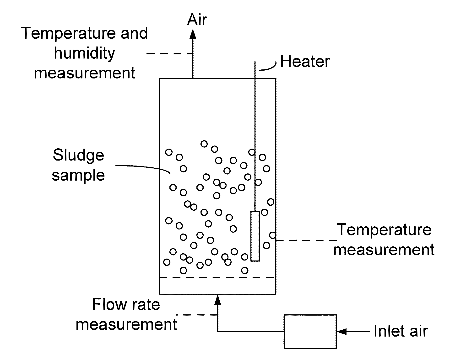
[0103]For the EMC determination, digested biosolids taken from Truckee Meadows Water Reclamation Facility (TMWRF), Reno, which has a typical moisture content of about 85% (wet basis) were used. The samples were kept in polyethylene bags and stored in a refrigerator at about 5° C. The static desiccator technique was used for EMC determination at constant temperature by exposing the biosolids samples to constant relative humidities maintained by saturated salt solutions.

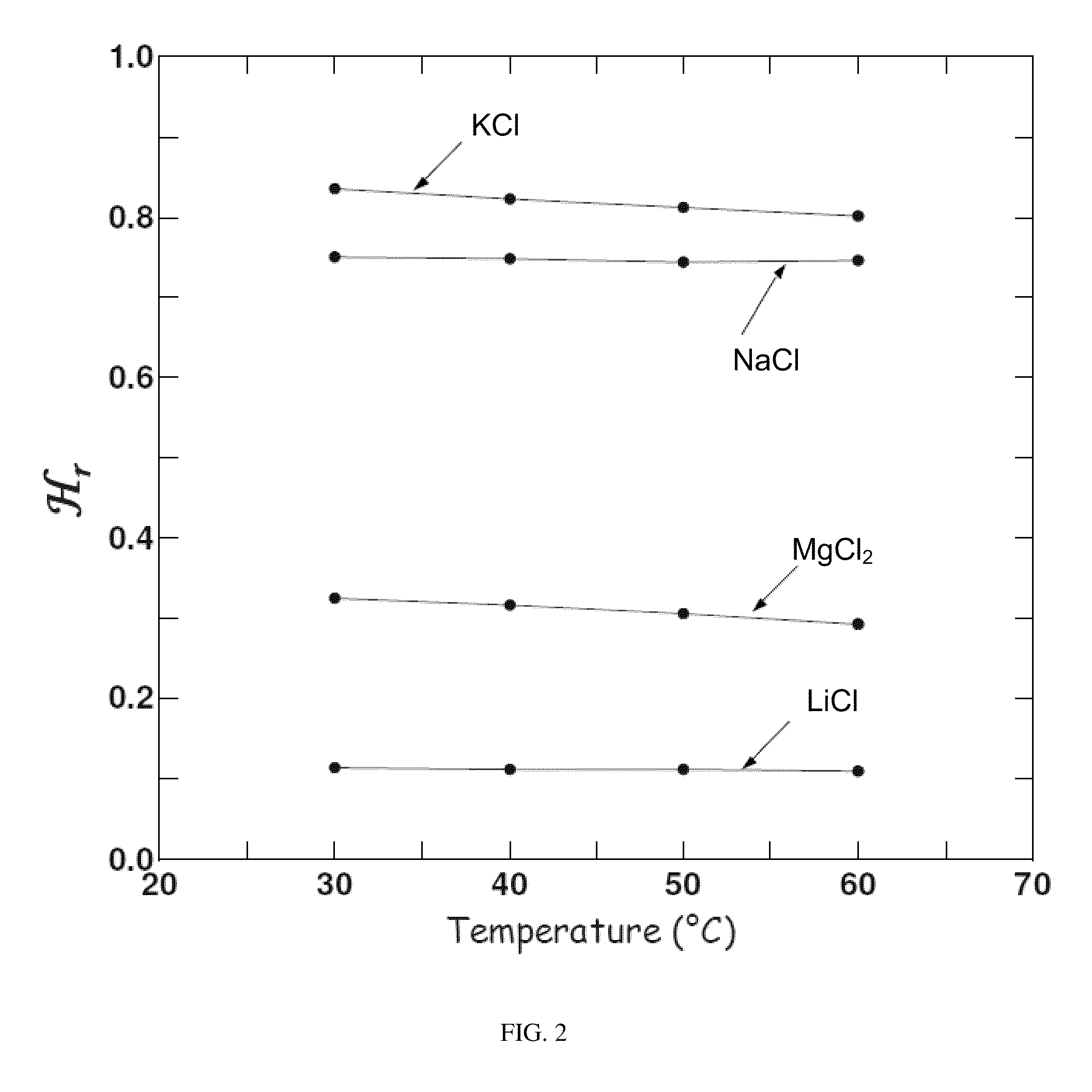
[0104]Glass desiccators containing salt solutions were used as humidity control chambers to fix the relative humidity levels from 0.10 to 0.84. These were kept in temperature controlled environments at four different temperatures (30, 40, 50, 60° C.). The four salts used were lithium chloride, magnesium chloride, sodium chloride, and potassium chloride. The salt solutions were prepared by dissol...

example 2

Integrated Process Flowsheet for Electricity Generation from Sludge

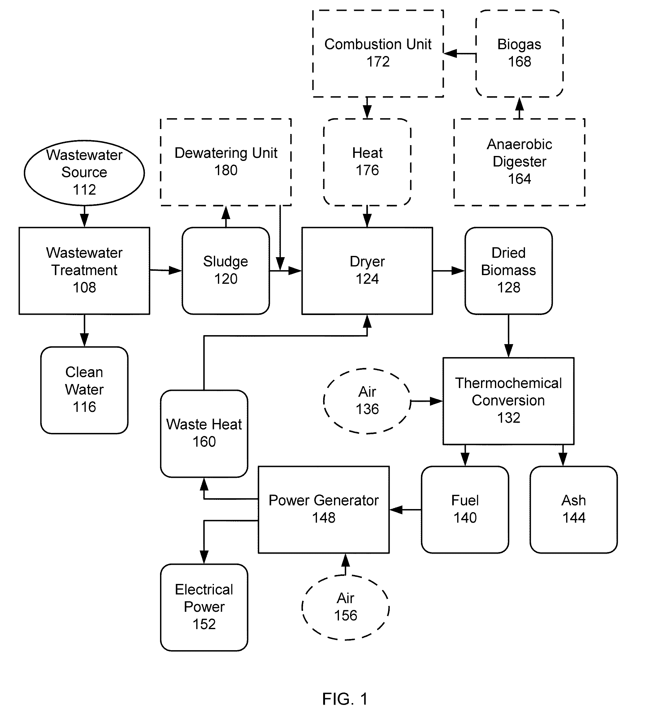
[0137]Drying the sludge is the first step in transforming the waste into electricity. The fuel is converted to electricity, such as by using air gasification to produce a fuel gas, followed by combustion of the gas in a generator, which in turn generates electrical power. Drying can require a substantial amount of heat, so careful heat integration throughout the process can be important for technical and economic feasibility. The integrated process includes a dryer, a gasifier, a gas generator, and heat exchangers for heat integration.

[0138]The present disclosure provides a complete flowsheet to maximize heat integration. The dried fuel is sent to a gasifier, which produces a fuel gas. The fuel gas is burned in a generator for production of electricity. Heat is recovered from the generator to be used in the dryer. FIG. 1 shows the simplified flowsheet for this process. The dryer has been considered in detail above, s...


PUM

PropertyMeasurementUnit
Temperatureaaaaaaaaaa

Abstract

The present disclosure provides, among other things, a system and process for drying a biosolid or sludge, such as wastewater sludge. The system and method include a fluidized bed dryer in which the sludge is dried. The fluidized bed includes bed media. In particular examples, the bed media is different than the sludge. The system and method can include additional features, such treating the sludge using a thermochemical process in a thermochemical reactor, such as a gasifier, to produce a fuel. The fuel is then combusted to produce energy and heat. The heat is recycled to the drier to help dry sludge. In particular examples, sludge input to the dryer is not first treated using a high-pressure dewatering technique. In some embodiments, the system and method include an anaerobic digester coupled to a combustion unit coupled to the dryer.

Description

CROSS REFERENCE TO RELATED APPLICATIONS[0001]This application claims the benefit of, and incorporates by reference, U.S. Provisional Patent Application No. 61 / 090,546, filed Aug. 20, 2008.FIELD[0002]The present disclosure relates, generally, to a method and a system for producing energy from wastewater sludge. In a specific example, the method and system can be used to produce energy or heat that can be used to reduce the external energy requirements of a sludge dryer.BACKGROUND[0003]Domestic, commercial, and industrial wastewater is generally collected through an extensive network of sewers and transported to wastewater treatment plants, usually Publicly Owned Treatment Works (POTW). At a POTW, the wastewater is treated to a regulated level of cleanliness, and then subsequently discharged, or used as reclaimed water (e.g., for irrigation). The treatment processes can vary from location to location. Variation can depend on the age of the facility, the facility's capacity, local regu...

Claims


Application Information

Patent Timeline
IPC IPC(8): F02C3/28F26B3/08
CPCF02C3/28F05D2220/75F26B3/088Y02E50/12F26B2200/02F26B2200/18Y02E20/18F26B23/028Y02E50/10
Inventor CORONELLA, CHARLES J.VASQUEZ, VICTOR R.
Owner BOARD OF RGT NEVADA SYST OF HIGHER EDUCATION ON BEHALF OF THE UNIV OF NEVADA RENO
Why Eureka
Try Eureka