Silicon-containing compound and organic electroluminescent device employing the same

a technology of organic electroluminescent devices and compound compounds, which is applied in the direction of thermoelectric devices, organic chemistry, transportation and packaging, etc., can solve the problems that the life, efficiency and power consumption of conventional electroluminescent devices employing hole injection layers and/or hole transport layers still needs to be improved, and achieves low driving voltage, high luminosity, and high efficiency

Active Publication Date: 2010-03-04
SAMSUNG DISPLAY CO LTD
View PDF0 Cites 35 Cited by
  • Summary
  • Abstract
  • Description
  • Claims
  • Application Information

AI Technical Summary

Benefits of technology

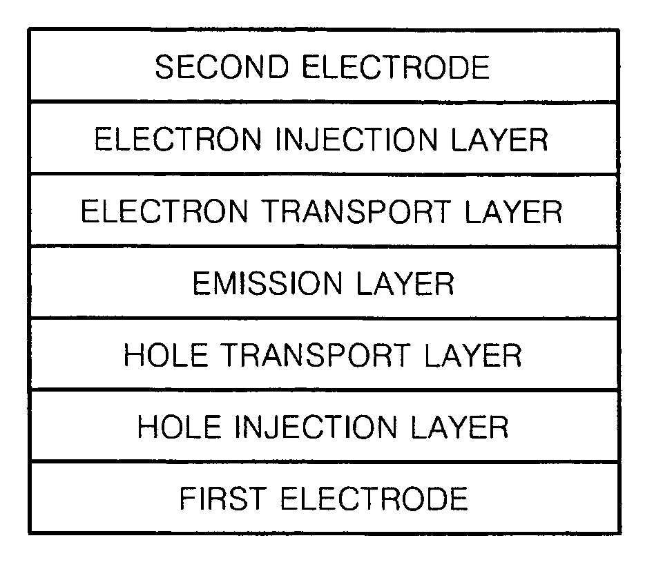
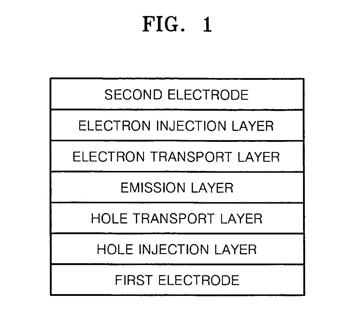
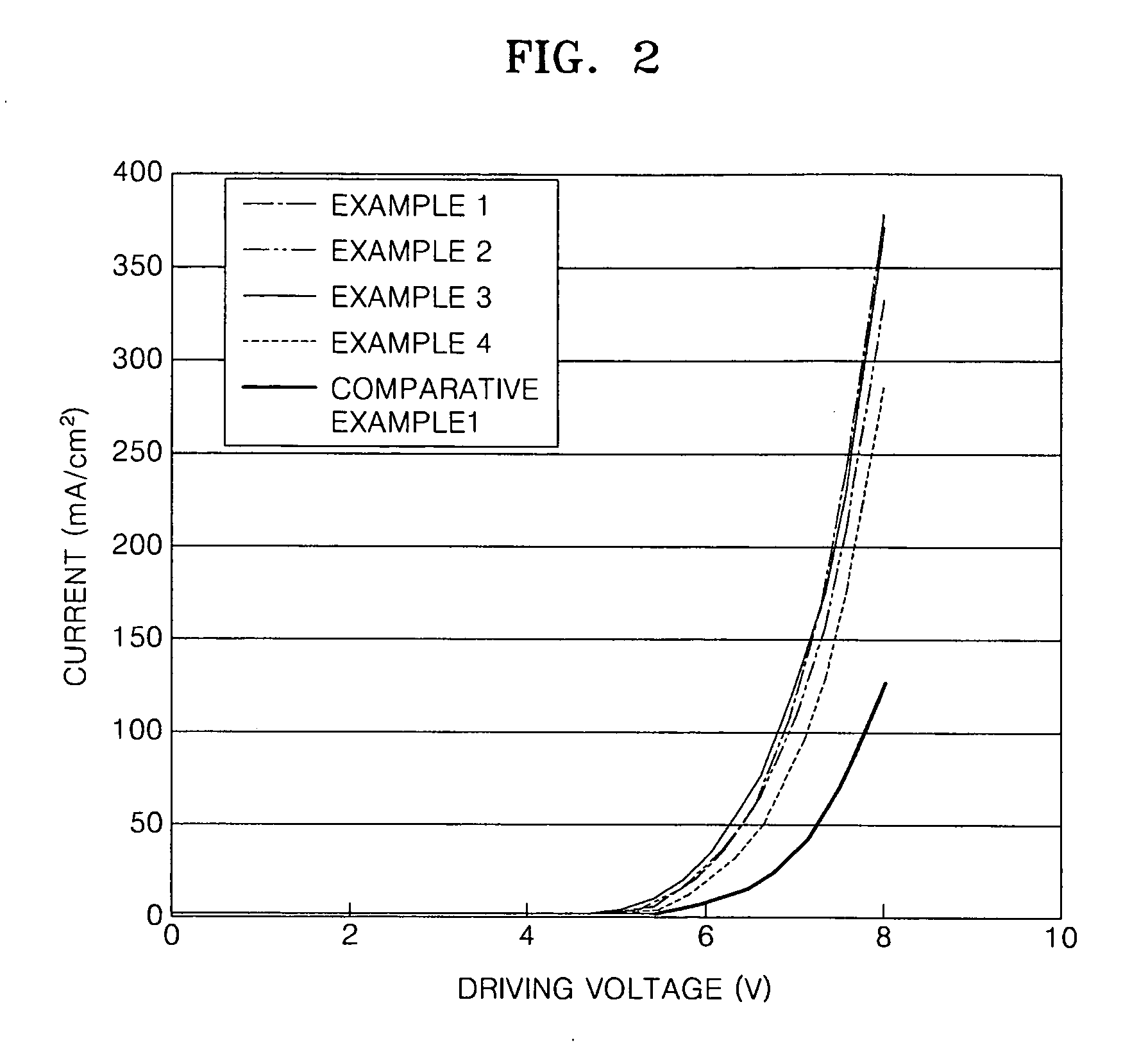
[0011]An embodiment of the present invention provides an organic electroluminescent device having high efficiency, a low driving voltage, and high luminosity and including an organic layer employing the silicon-containing compound, and a flat panel apparatus including the organic electroluminescent device.

Problems solved by technology

However, organic electroluminescent devices employing conventional hole injection layer and / or hole transport layer forming materials still needs to be improved in terms of lifetime, efficiency, and power consumption.

Method used


Image

  • Silicon-containing compound and organic electroluminescent device employing the same
  • Silicon-containing compound and organic electroluminescent device employing the same
  • Silicon-containing compound and organic electroluminescent device employing the same

Examples


synthesis example 1

Synthesis of Intermediate 1

[0049]2.433 g (10 mmol) of phenylcarbazole was added to 100 mL of 80% acetic acid, and then 1.357 g (5.35 mmol) of iodine (I2) and 0.333 g (1.46 mmol) of ortho-periodic acid (H5IO6) were added thereto in a solid state. The resultant mixture was stirred in a nitrogen atmosphere at 80 C for 2 hours.

[0050]After the reaction was finished, the reaction solution was extracted using 50 mL of ethylether three times. The collected organic layer was dried over magnesium sulfate (MgSO4) and a solvent was evaporated to obtain the residue. The residue was refined by column chromatography and 3.23 g (yield 87%) of Intermediate 1 having the following structure was obtained. Intermediate 1 was a white solid:

[0051]1H NMR (CDCl3, 300 MHz) δ (ppm) −8.43 (d, 1H), 8.05 (d, 1H), 7.62 (dd, 1H), 7.61-7.75 (m, 2H), 7.51-7.43 (m, 3H), 7.41-7.35 (m, 2H), 7.27 (dd, 1H), 7.14 (d, 1H)

synthesis example 2

Synthesis of Intermediate 2

[0052]Intermediate 2 having the following structure was prepared in the same manner as in Synthesis Example 1, except that naphthylcarbazole was used instead of phenylcarbazole. The yield of Intermediate 2 was 85%:

[0053]1H NMR (CDCl3, 300 MHz) δ (ppm) −8.29 (s, 1H), 8.13 (d, 1H), 7.92 (d, 1H), 7.80-7.73 (m, 3H), 7.59-7.49 (m, 5H), 7.37-7.29 (m, 3H)

synthesis example 3

Synthesis of Intermediate 3

[0054]Intermediate 3 having the following structure was prepared in the same manner as in Synthesis Example 1, except that biphenylcarbazole was used instead of phenylcarbazole. The yield of Intermediate 3 was 62%:

[0055]1H NMR (CDCl3, 300 MHz) δ (ppm) −8.30 (s, 1H), 8.13-8.11 (m, 1H), 7.74 (d, 1H), 7.59-7.53 (m, 3H), 7.40-7.28 (m, 8H), 6.64-6.60 (m, 2H)


PUM

PropertyMeasurementUnit
temperatureaaaaaaaaaa
sizeaaaaaaaaaa
luminescent efficiencyaaaaaaaaaa

Abstract

Provided are a silicon-containing compound having carbazole and fluorene in its molecule and an organic electroluminescent device including an organic layer employing the same. The silicon-containing compound is represented by the following formula:
The silicon-containing compound has excellent electrical characteristics and a charge transporting capability, the silicon-containing compound can be used as a hole injecting material, a hole transporting material, and/or a light emitting material that are suitable for all-color fluorescent and phosphorescent organic light emitting devices such as red, green, blue, and white fluorescent and phosphorescent organic light emitting devices. When the silicon-containing compound is used to manufacture an organic electroluminescent device, the organic electroluminescent device has a high efficiency, a low driving voltage, high luminosity, and a long lifetime.

Description

CROSS-REFERENCE TO RELATED PATENT APPLICATION AND CLAIM OF PRIORITY[0001]This application claims the benefit of Korean Patent Application No. 10-2008-0086800, filed on Sep. 3, 2008, in the Korean Intellectual Property Office, the disclosure of which is incorporated herein in its entirety by reference.BACKGROUND OF THE INVENTION[0002]1. Field of the Invention[0003]The present invention relates to a silicon-containing compound and an organic electroluminescent device employing the same.[0004]2. Description of the Related Art[0005]Electroluminescent devices are a self-emission type display device and have a wide viewing angle, a high contrast ratio, and a short response time. Due to such characteristics, electroluminescent devices are getting more attention.[0006]Electroluminescent devices are generally classified into inorganic electroluminescent devices including an emitting layer employing an inorganic compound and organic electroluminescent devices including an emitting layer emplo...

Claims


Application Information

Patent Timeline
Patent Type & Authority Applications(United States)
IPC IPC(8): H01L51/54C07F7/02
CPCC07F7/0812H01L51/0072H01L51/0081H01L51/0094Y10T428/1045H01L51/5048H01L51/5088Y10T428/1014Y10T428/1068H01L51/5012C09K2323/023C09K2323/033C09K2323/053H10K85/6572H10K85/324H10K85/40H10K50/14H10K50/17H10K50/11C07F7/08C07F7/10C09K11/06
Inventor HWANG, SEOK-HWANKIM, YOUNG-KOOKKWAK, YOON-HYUNYI, JEOUNG-INLEE, JONG-HYUK
Owner SAMSUNG DISPLAY CO LTD
Why Eureka
Try Eureka