Diaphragm for speaker, frame for speaker, dust cap for speaker, speaker and apparatus using them, and method for manufacturing component for speaker

a technology for dust caps and diaphragms, which is applied in the direction of transducer diaphragms, electromechanical transducers, instruments, etc., can solve the problems of insufficient strength to enhance the sound quality, difficult to satisfy the market demand, and difficult to reduce the cost of components, etc., to achieve high elastic modulus, high productivity, and high strength

Active Publication Date: 2010-03-11
PANASONIC INTELLECTUAL PROPERTY MANAGEMENT CO LTD
View PDF19 Cites 25 Cited by
  • Summary
  • Abstract
  • Description
  • Claims
  • Application Information

AI Technical Summary

Benefits of technology

[0029]The speaker diaphragm of the present invention includes a resin and a cellulose fiber, where the cellulose fiber is a bamboo fiber. According to such configuration, the speaker diaphragm of high productivity having high strength and high elastic modulus is obtained.
[0030]The speaker frame of the present invention is resolved with lack of strength, and provides a speaker having a wide adjustment range of speaker characteristics and sound quality when used in speakers.
[0031]The speaker frame of the present invention includes a resin and a cellulose fiber, where the cellulose fiber is a bamboo fiber. According to such configuration, the speaker frame of high productivity having high strength and high elastic modulus is obtained.
[0032]The speaker dust cap of the present invention is resolved with lack of strength, and provides a speaker having a wide adjustment range of speaker characteristics and sound quality when used in speakers.
[0033]The speaker dust cap of the present invention includes a resin and a cellulose fiber, where the cellulose fiber is a bamboo fiber. According to such configuration, the speaker dust cap of high productivity having high strength and a high elastic modulus is obtained.
[0034]A method for manufacturing a speaker component of the present invention includes a miniaturization step, a compounding step, and a molding step, and in the miniaturization step, the fiber is partially miniaturized to the microfibrillated state to generate a microfibrillated fiber containing moisture; in the compounding step, the moisture contained in the microfibrillated fiber and the granulated resin are substituted to generate a compound containing the microfibrillated fiber and the resin; and in the molding step, the compound is injection-molded. According to such manufacturing method, the secondary aggregation of the resin and the fiber is prevented, and the speaker component with enhanced dispersibility is obtained. Furthermore, a speaker with excellent external appearance in which the degree of freedom in the adjustment of sound quality is large, and the humidity resistance and water resistance reliabilities are improved is provided by using the obtained speaker component.

Problems solved by technology

However, each has problems, and it is difficult to satisfy the market demand such as lower distortion, wider band, and higher dynamic range.
Furthermore, in the production of diaphragm 101 made of paper, lowering the cost of the component is difficult as great number of steps of papermaking is required.
However, diaphragm 101 of the related art has a problem in that the strength is insufficient to enhance the sound quality.
However, frame 107 made of the iron plate has problems in that magnetic leakage is large, and the external appearance also lacks in sophisticated image.
However, frame 107 made of the material of aluminum die-cast has a problem in that it is very expensive.
However, such frame 107 made of the resin of the related art may be light weight, but does not have enough rigidity with only the resin of a base material.
However, the specific gravity of frame 107 also increases, and thus the weight of frame 107 becomes heavy.
Moreover, a problem in that the effect of absorbing unnecessary vibration reduces arises since the internal loss of frame 107 becomes small.
However, in the method for manufacturing the speaker component such as diaphragm 101 of the related art, diaphragm 101 made of a resin has a problem in that adjustment of the characteristics and the sound quality for speaker 110 can only be carried out within a range of the characteristic value of the material of the resin being used, and only a standardized sound can be generated.

Method used


Image

  • Diaphragm for speaker, frame for speaker, dust cap for speaker, speaker and apparatus using them, and method for manufacturing component for speaker
  • Diaphragm for speaker, frame for speaker, dust cap for speaker, speaker and apparatus using them, and method for manufacturing component for speaker
  • Diaphragm for speaker, frame for speaker, dust cap for speaker, speaker and apparatus using them, and method for manufacturing component for speaker

Examples


embodiment 1

[0100]Embodiment 1 of the present invention will be described with reference to

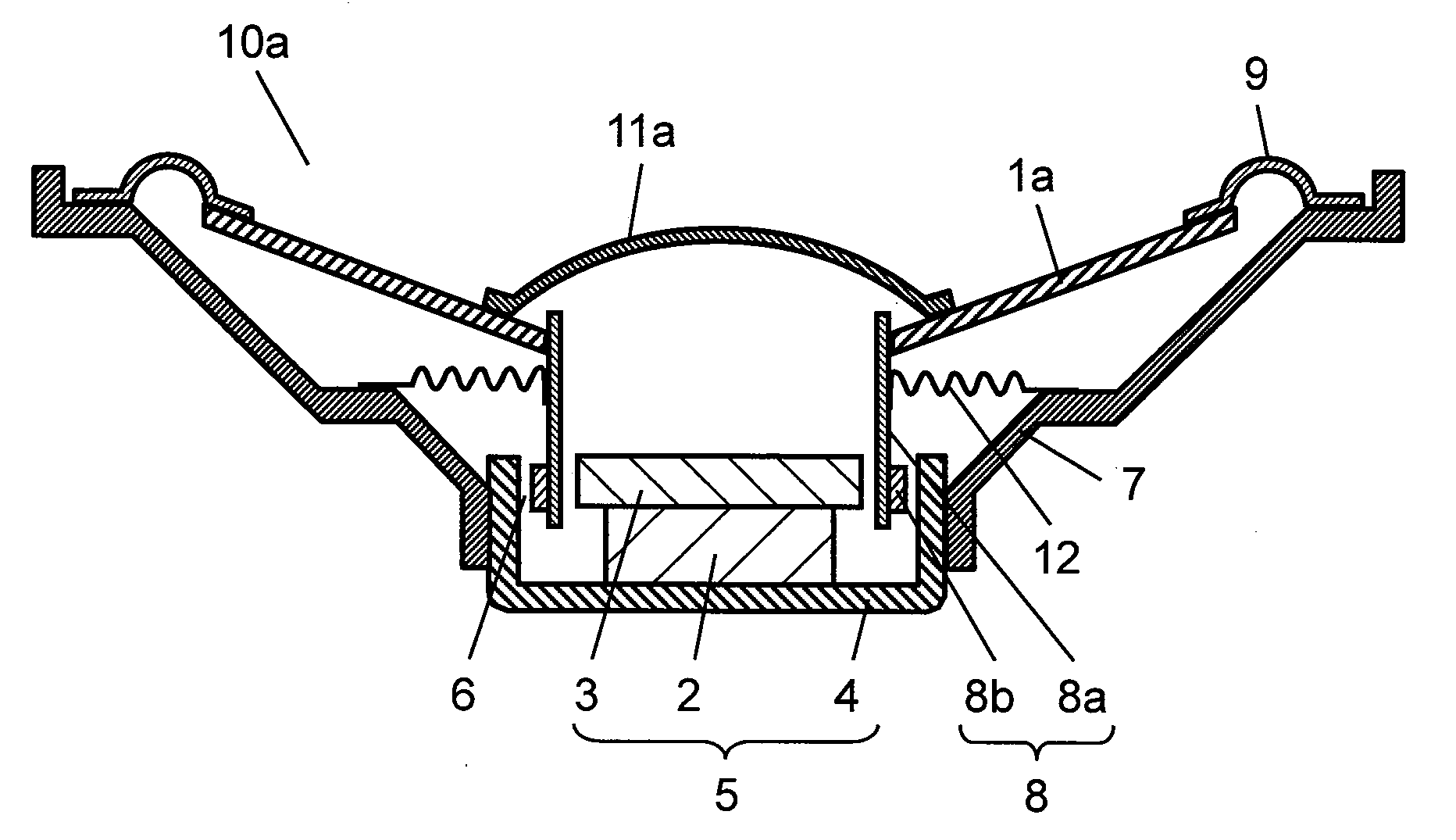
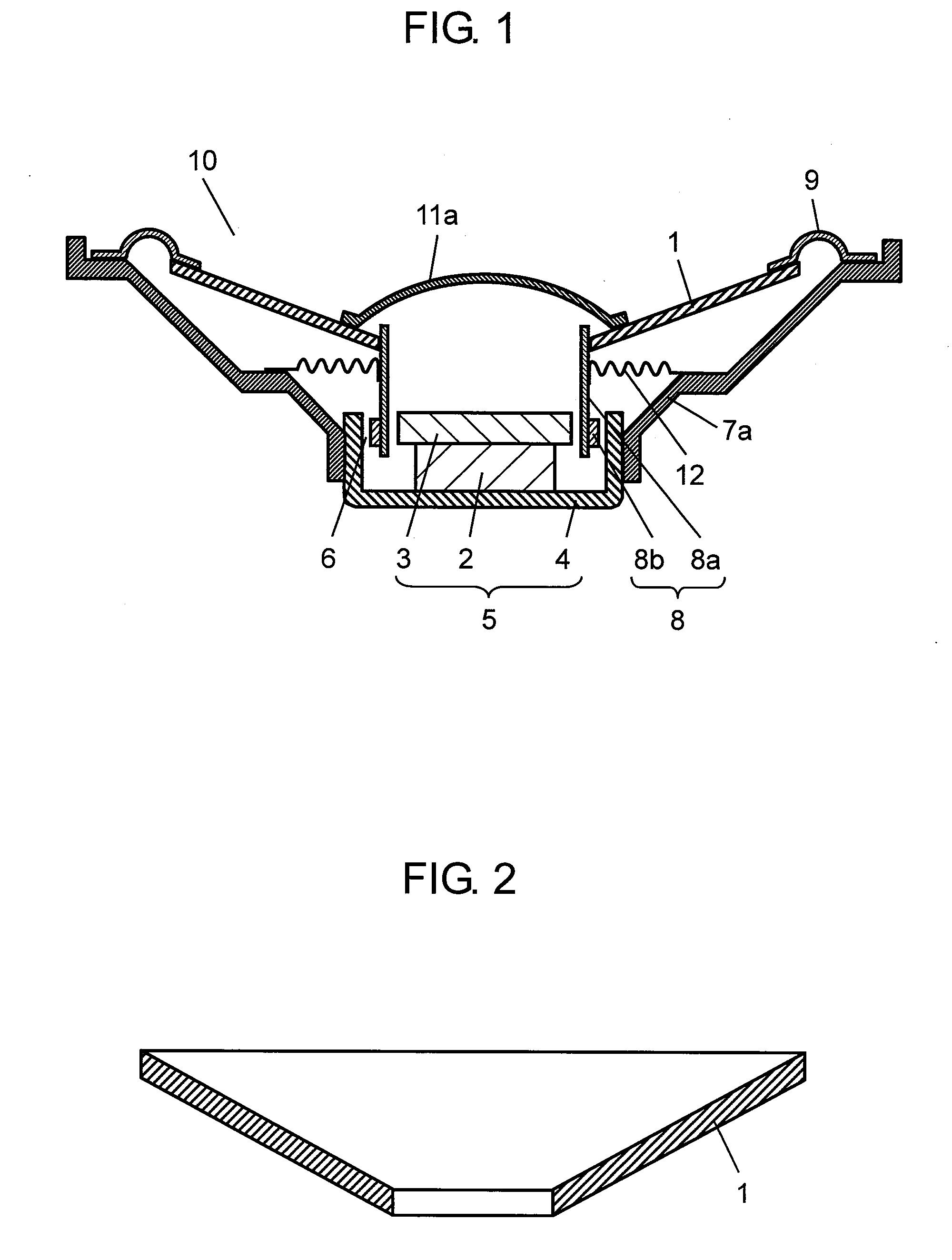
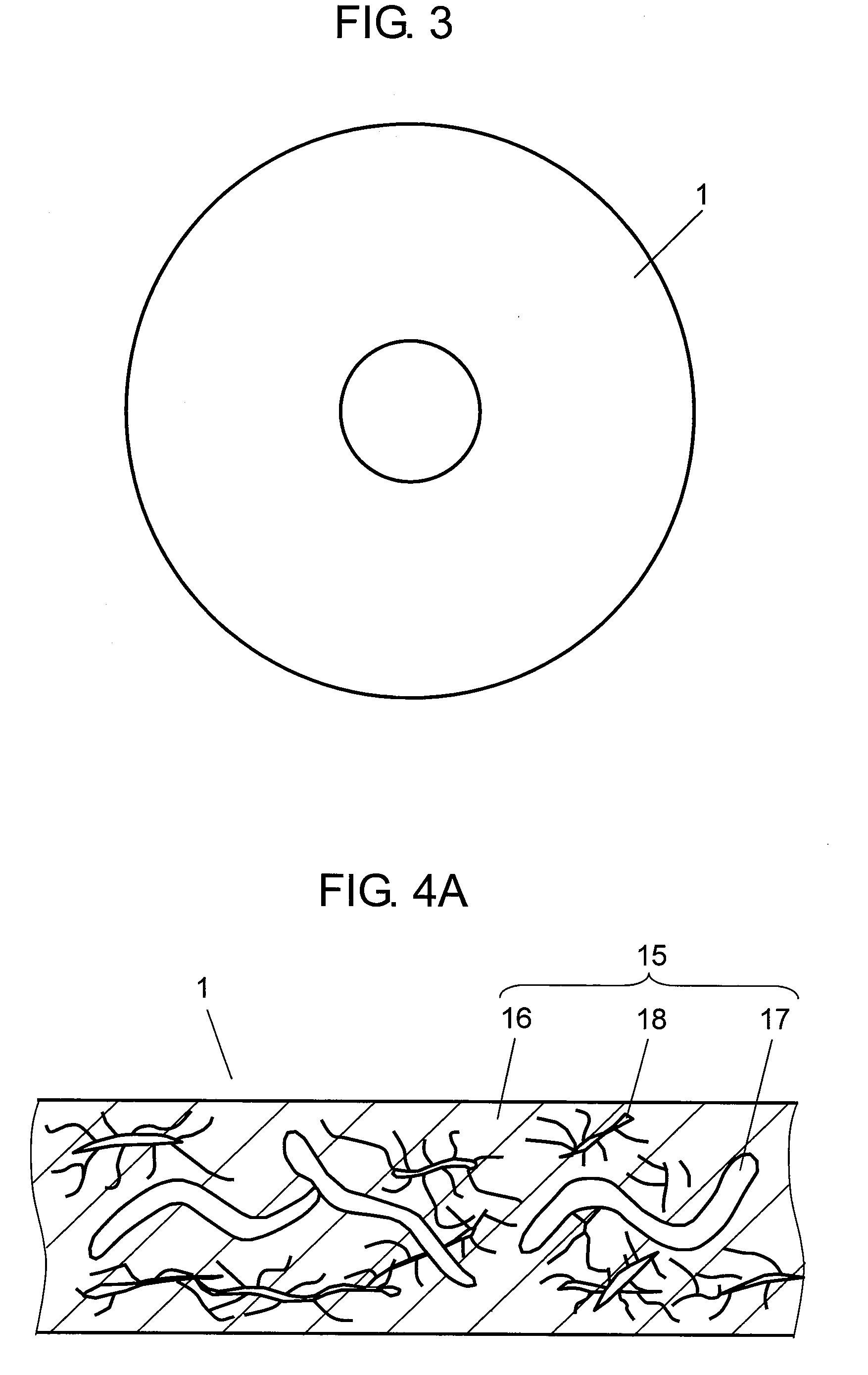
[0101]FIG. 1 to FIG. 4. FIG. 1 is a cross-sectional view of speaker 10 according to Embodiment 1 of the present invention. FIG. 2 is a cross-sectional view of speaker diaphragm 1 (hereinafter referred to as diaphragm 1) used in speaker 10 shown in FIG. 1. FIG. 3 is a plan view of diaphragm 1 shown in FIG. 2. FIG. 4A is a partially detailed cross-sectional view of diaphragm 1 shown in FIG. 2. FIG. 4B is a partially detailed cross sectional view of speaker diaphragm 1 of another aspect used in speaker 10 shown in FIG. 1.

[0102]As shown in FIG. 1, speaker 10 includes diaphragm 1, magnetic circuit 5, speaker frame 7a (hereinafter referred to as frame 7a), and voice coil 8. Magnetic circuit 5 is configured by sandwiching polarized magnet 2 between upper plate 3 and yoke 4. Frame 7a is coupled to yoke 4. An outer periphery of diaphragm 1 is coupled to an outer peripheral portion of frame 7a by way of edge 9. One...

embodiment 2

[0146]Embodiment 2 of the present invention will be described using the drawings. The configurations similar to Embodiment 1 are denoted with similar reference numerals, and the detailed description will be omitted.

[0147]FIG. 5 is a cross-sectional view of speaker 10a according to Embodiment 2 of the present invention. FIG. 6 is a cross-sectional view of speaker frame 7 (hereinafter referred to as frame 7) used in speaker 10a shown in FIG. 5. FIG. 7 is a partially detailed cross sectional view of frame 7 shown in FIG. 6.

[0148]As compared to speaker 10 according to Embodiment 1, speaker 10a according to Embodiment 2 has diaphragm 1 replaced with speaker diaphragm 1a (hereinafter referred to as diaphragm 1a), and frame 7a replaced with frame 7. Other configurations of speaker 10a according to Embodiment 2 have configurations similar to speaker 10 according to Embodiment 1. Diaphragm1a includes resin 16 but does not include bamboo fiber 17. Similar to diaphragm 1, frame 7 is made from ...

embodiment 3

[0177]Embodiment 3 of the present invention will be described using the drawings. The configurations similar to Embodiments 1 and 2 are denoted with similar reference numerals, and the detailed description will be omitted.

[0178]FIG. 8 is a cross-sectional view of speaker 10b according to Embodiment 3 of the present invention. FIG. 9 is a cross-sectional view of speaker dust cap 11 (hereinafter referred to as cap 11) used in speaker 10b shown in FIG. 8. FIG. 10 is a partially detailed cross sectional view of cap 11 shown in FIG. 9.

[0179]As compared to speaker 10 according to Embodiment 1, speaker 10b according to Embodiment 3 has diaphragm 1 replaced with speaker diaphragm 1a, and cap 11a replaced with cap 11. Other configurations of speaker 10b according to Embodiment 3 have configurations similar to speaker 10 according to Embodiment 1. As compared to speaker 10a according to Embodiment 2, speaker 10b according to Embodiment 3 has frame 7 replaced with frame 7a, and cap 11a replace...


PUM

PropertyMeasurementUnit
lengthaaaaaaaaaa
degree of freedomaaaaaaaaaa
lengthaaaaaaaaaa

Abstract

A speaker diaphragm is configured by a compound mixed with resin and bamboo fiber. The diaphragm satisfying the advantage of the bamboo fiber of high sound quality and a large degree of freedom in the setting of the characteristic value of the diaphragm and the advantage of the diaphragm made of a resin with improved humidity resistance reliability and strength, excellent external appearance, and enhanced productivity and dimension stability is obtained.

Description

[0001]THIS APPLICATION IS A U.S. NATIONAL PHASE APPLICATION OF PCT INTERNATIONAL APPLICATION PCT / JP2007 / 074497, filed Dec. 20, 2007.TECHNICAL FIELD[0002]The present invention relates to a speaker diaphragm, a speaker frame, and a speaker dust cap used in various acoustic equipments or in video equipments; a speaker, a stereo system, or a television set as well as a device such as a moving body using the same; and a method for manufacturing a speaker component.BACKGROUND ART[0003]A speaker of the related art will be described below with reference to FIG. 14. FIG. 14 is a cross-sectional view of a speaker of the related art.[0004]As shown in FIG. 14, speaker 110 includes speaker diaphragm 101 (hereinafter referred to as diaphragm 101), magnetic circuit 105, speaker frame 107 (hereinafter referred to as frame 107), and voice coil 108. Magnetic circuit 105 is configured by sandwiching polarized magnet 102 between upper plate 103 and yoke 104. Frame 107 is coupled to yoke 104. An outer p...

Claims


Application Information

Patent Timeline
Patent Type & Authority Applications(United States)
IPC IPC(8): H04R7/00B29C45/00
CPCH04R7/12H04R31/003H04R2307/029H04R2307/021H04R2307/025H04R2231/001
Inventor KAJIHARA, YOSHIMICHIMIZONE, SHINYAMIMURA, KAZUYOSHISABATO, TAKASHINISHIMURA, KAZUAKI
Owner PANASONIC INTELLECTUAL PROPERTY MANAGEMENT CO LTD
Why Eureka
Try Eureka