
Catalyst system to be used in automobile exhaust gas purification apparatus, exhaust gas purification apparatus using the same and exhaust gas purification method

a catalyst system and exhaust gas technology, applied in the direction of metal/metal-oxide/metal-hydroxide catalysts, machines/engines, etc., can solve the problems of sintering of exhaust gas purification catalyst components, difficult to maintain constant engine combustion state, and inability to purify toxic substances by oxygen utilization, etc., to achieve excellent purification performance

Active Publication Date: 2010-03-11
DAIICHI KIGENSO KAGAKU KOGYO CO LTD +1
View PDF16 Cites 46 Cited by
  • Summary
  • Abstract
  • Description
  • Claims
  • Application Information

AI Technical Summary

Benefits of technology

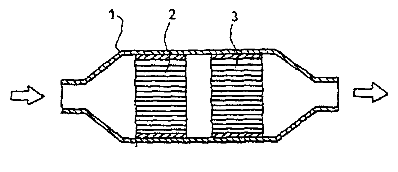
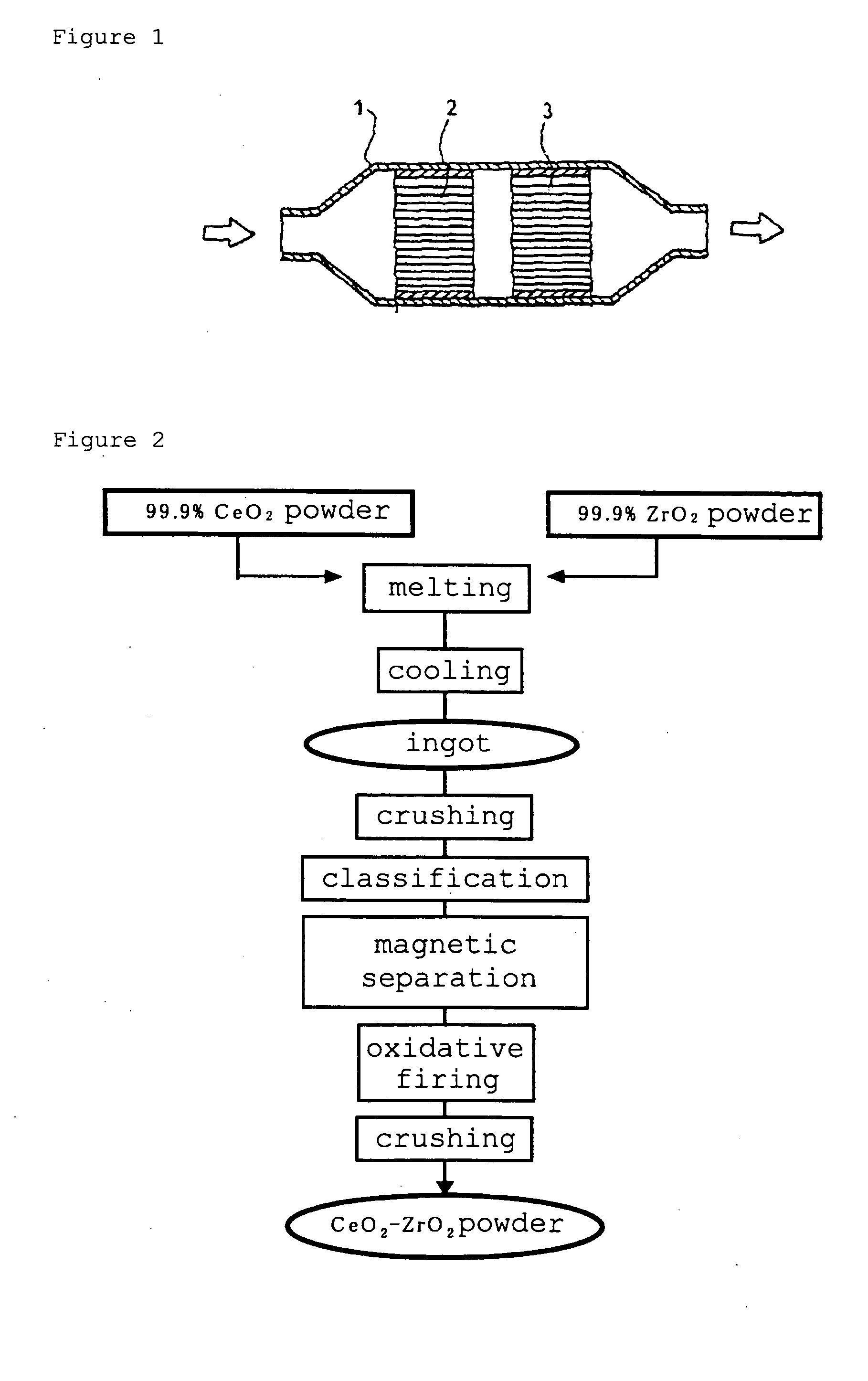
The present invention provides a catalyst system for purifying nitrogen oxides in exhaust gas from automobiles. The system uses two or more exhaust gas purification catalysts, with one catalyst containing a cerium-zirconium composite oxide with a pyrochlore phase in the crystal structure. The catalysts are arranged in an exhaust gas passage with one catalyst positioned at the upstream side and another at the downstream side. The first catalyst is supported on an inorganic structural carrier and has a small specific surface area, while the second catalyst contains one or more active metal species, such as platinum, palladium, or rhodium, and has a specific surface area of equal to or smaller than 20 m2 / g. The cerium-zirconium composite oxide has a pyrochlore phase in the crystal structure and can efficiently decompose nitrogen oxides, even when the hydrocarbon concentration in the exhaust gas varies. The system can purify nitrogen oxides, reduce CO and HC in the exhaust gas simultaneously. The inorganic structural carrier can be a honeycomb structure or a flow-through-type carrier. The system can be used in automobile exhaust gas purification apparatuses and has excellent purification capabilities.

Problems solved by technology

However, in the case of an automobile, because of variation of running circumstances depending on a road jam state, it is difficult to maintain an engine combustion state constant, and oxygen concentration in exhaust gas also varies every second.
Accordingly, there was a case where purification of the toxic substances by utilization of oxygen became impossible when oxygen concentration was lowered.
On the other hand, the just-under-type may encounter a case where temperature of exhaust gas exceeds 1000° C., which may incur sintering of exhaust gas purification catalyst components.
Such a state of large theoretical air / fuel ratio results in increase in NOx generation amount, and purification thereof was difficult by the conventional TWC.
In the case where the conventional TWC is used in the lean atmosphere, there was a problem that a large quantity of NOx is discharged, due to influence of excess oxygen, resulting in insufficient purification action.

Method used


Image

  • Catalyst system to be used in automobile exhaust gas purification apparatus, exhaust gas purification apparatus using the same and exhaust gas purification method
  • Catalyst system to be used in automobile exhaust gas purification apparatus, exhaust gas purification apparatus using the same and exhaust gas purification method
  • Catalyst system to be used in automobile exhaust gas purification apparatus, exhaust gas purification apparatus using the same and exhaust gas purification method

Examples


example 1

[0164]Catalyst slurry was prepared by adjusting the component amount so that the above catalyst materials become the predetermined coating amount, based on unit volume of the following one-piece structural carrier, and by mixing with suitable amount of aqueous medium for 5 hours with a ball mill. Thus prepared slurry was coated on the one-piece structural type carrier by a wash-coat method. Two-coat structure was obtained by coating the second catalyst layer on the first catalyst layer. This was subjected to drying, and firing at 500° C. for 1 hour to obtain the one-piece structural type catalyst. Coated amount of catalyst components, based on unit volume, contained in each layer, is shown in Table 2. It should be noted that values in Table 2 represent “g / L”.

[0165]Kind of the one-piece structural type catalyst: A flow-through-type carrier

[0166]Volume of the one-piece structural type catalyst: 645 cc (height: 95 mm*diameter: 93 mm)

[0167]Material of the one-piece structural type catal...

example 2

[0170]Catalyst slurry was prepared by adjusting the component amount so that the above catalyst materials become the predetermined coating amount, based on unit volume of the following one-piece structural carrier, and by mixing with suitable amount of aqueous medium for 5 hours with a ball mill. Thus prepared slurry was coated on the one-piece structural type carrier by a wash-coat method. Similarly as in Example 1, except that coating was changed to a single coat, the one-piece structural type catalyst was obtained. Coated amount of catalyst components, based on unit volume is shown in Table 2.

[0171]Although two catalysts containing the cerium-zirconium-type composite oxide (A) of a melting-type at high temperature, of Example 1, were used to constitute an apparatus as the TWC, target value of NOx purification rate was not attained. Accordingly, using this as the downstream side catalyst (Table 2), and a conventional TWC catalyst (Table 1) was arranged at the upstream side thereof...

examples 3 and 4

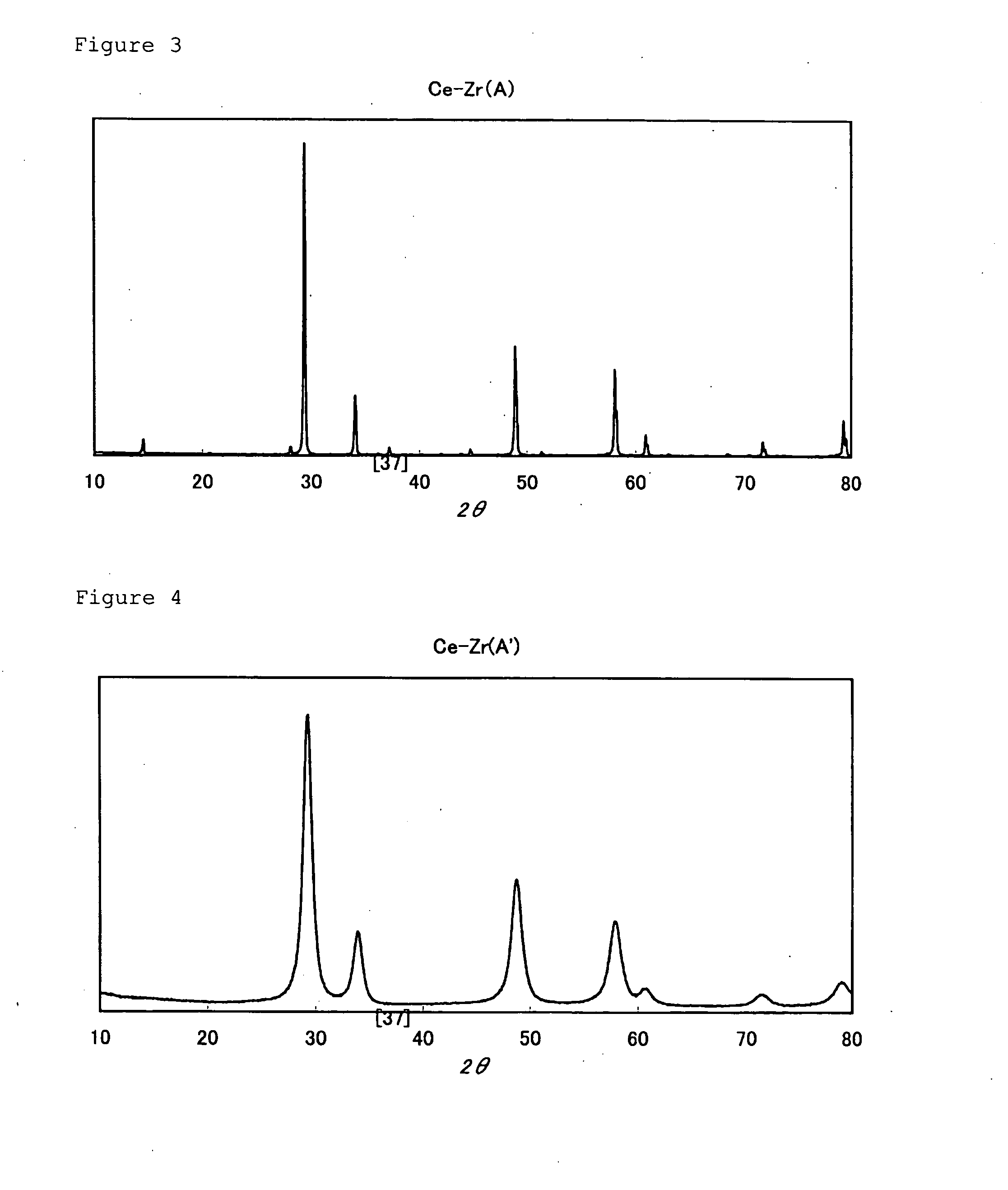
[0184]One-piece structural type catalysts were obtained by using the catalyst materials used in Example 1 and a similar method as in Example 1, and by using a catalyst composition containing Ce—Zr(A) as the downstream side catalyst in Example 3, and by using a catalyst composition containing Ce—Zr(A′) and Ce—Zr (A) in Example 4. Coated amounts of catalyst components, based on unit volume, contained in each layer, are shown in Table 3 and Table 4. contained in each layer. Table 3 shows composition of the upstream side catalyst, and Table 4 shows composition of the downstream side catalyst. It should be noted that value in Tables 3 and 4 show “g / L”.

[The One-Piece Structural Carrier for the Upstream Side Catalyst]

[0185]Kind of the one-piece structural type catalyst: A flow-through-type carrier

[0186]Volume of the one-piece structural type catalyst: 550 cc (height: 50 mm×diameter: 118.4 mm)

[0187]Material of the one-piece structural type catalyst: Cordierite

[0188]Cell density of the one-p...


PUM

PropertyMeasurementUnit
particle sizeaaaaaaaaaa
specific surface areaaaaaaaaaaa

Abstract

A catalyst system to be used in an automobile exhaust gas purification apparatus which exerts excellent purification capability to a nitrogen oxide, even when hydrocarbon concentration varies, by subjecting exhaust gas discharged from an automotive internal engine to contacting with a catalyst, an exhaust gas purification apparatus using the same, and an exhaust gas purification method.A catalyst system etc. to be used in an automobile exhaust gas purification apparatus, composed by using two or more exhaust gas purification catalysts, containing a first catalyst supported on an inorganic structural carrier and a second catalyst other than this, characterized by having the first catalyst supported on apart of the inorganic structural carrier positioned at the upstream side, when arranged in an exhaust gas passage; on the other hand having the second catalyst supported on a part of the inorganic structural carrier, positioned at the downstream side, when arranged in an exhaust gas passage; and containing a cerium-zirconium-type composite oxide (A) having a pyrochlore phase in the crystal structure.

Description

BACKGROUND OF THE INVENTION[0001]1. Field of the Invention[0002]The present invention relates to a catalyst system to be used in an automobile exhaust gas purification apparatus, an exhaust gas purification apparatus using the same, and an exhaust gas purification method, and in more detail, the present invention relates to a catalyst system to be used in an automobile exhaust gas purification apparatus which exerts excellent purification capability to a nitrogen oxide, even when hydrocarbon concentration varies, by subjecting exhaust gas discharged from an automotive internal engine to contacting with a catalyst, an exhaust gas purification apparatus using the same, and an exhaust gas purification method.[0003]2. Description of the Prior Art[0004]Exhaust gas discharged from an internal combustion engine of an automobile or the like, or a combustion engine of a boiler or the like, contains toxic substances such as a hydrocarbon (HC), carbon monoxide (CO), a nitrogen oxide (NOx), and...

Claims


Application Information

Patent Timeline
Patent Type & Authority Applications(United States)
IPC IPC(8): B01D53/94B01J23/10
CPCB01D53/9409Y02T10/22B01D53/9468B01D53/9477B01D2251/202B01D2255/102B01D2255/206B01D2255/407B01D2255/9202B01D2255/9207B01D2258/014B01J23/10B01J23/63B01J37/0036B01J37/0244B01J37/0248B01J37/031B01D53/945Y02A50/20Y02T10/12B01D53/94F01N3/10
Inventor KOHARA, AKIRAHIRASAWA, YOSHIROKATOH, KATSUAKI
Owner DAIICHI KIGENSO KAGAKU KOGYO CO LTD
Learn More