Selective Catalytic NOx Reduction Process and Control System

a control system and catalytic nox technology, applied in the direction of separation process, lighting and heating apparatus, dispersed particle separation, etc., can solve the problems of reducing the efficiency of urea utilization, and reducing the concentration of nitrogen oxides

Active Publication Date: 2010-03-11
FUEL TECH
View PDF15 Cites 12 Cited by
  • Summary
  • Abstract
  • Description
  • Claims
  • Application Information

AI Technical Summary

Benefits of technology

[0011]The present invention provides a process for reducing the concentration of nitrogen oxides in combustion gases from a plurality of turbines or other combustors, each of which has an associated selective catalytic NOx reduction catalyst effective for utilizing gasified urea, the process comprising: heating aqueous urea at conditions of temperature and pressure for a time effective to gasify the urea and water by mixing the aqueous urea with a heated gas stream in amounts relative to the amounts of urea and water to produce a first gasified reductant stream comprising a predetermined mass and concentration of ammonia; monitoring the demand for urea at each of the plurality of turbines; feeding the first gasified reductant stream to each turb

Problems solved by technology

These are not clean fuels according to criteria that utilities normally consider.
In addition, some compounds present in the gas and are known to clog NOx reduction catalysts and shorten the life of the turbines.
The net effect for operators is that utilization of this low-cost fuel can present additional costs in terms of shortened turbine life, corroded ductwork and fouled catalysts.
Unless these costs can be recovered by taking good advantage of the energy value of these fuels, the environment will suffer and their energy value will likely be replaced with imported petroleum.
However, SCR units typically require the use of ammonia as a reducing reagent, and it is a common problem that ammonia is difficult and dangerous to store, especially in populated areas.
Thus, the use of ammonia generators such as described in U.S. Pat. No. 7,090,810 to Sun, et al., and U.S. Pat. No. 6,077,491 to Cooper, et al., are often required, but their control for multiple turbine units has not been addressed and can be more

Method used


Image

  • Selective Catalytic NOx Reduction Process and Control System
  • Selective Catalytic NOx Reduction Process and Control System
  • Selective Catalytic NOx Reduction Process and Control System

Examples


Embodiment Construction

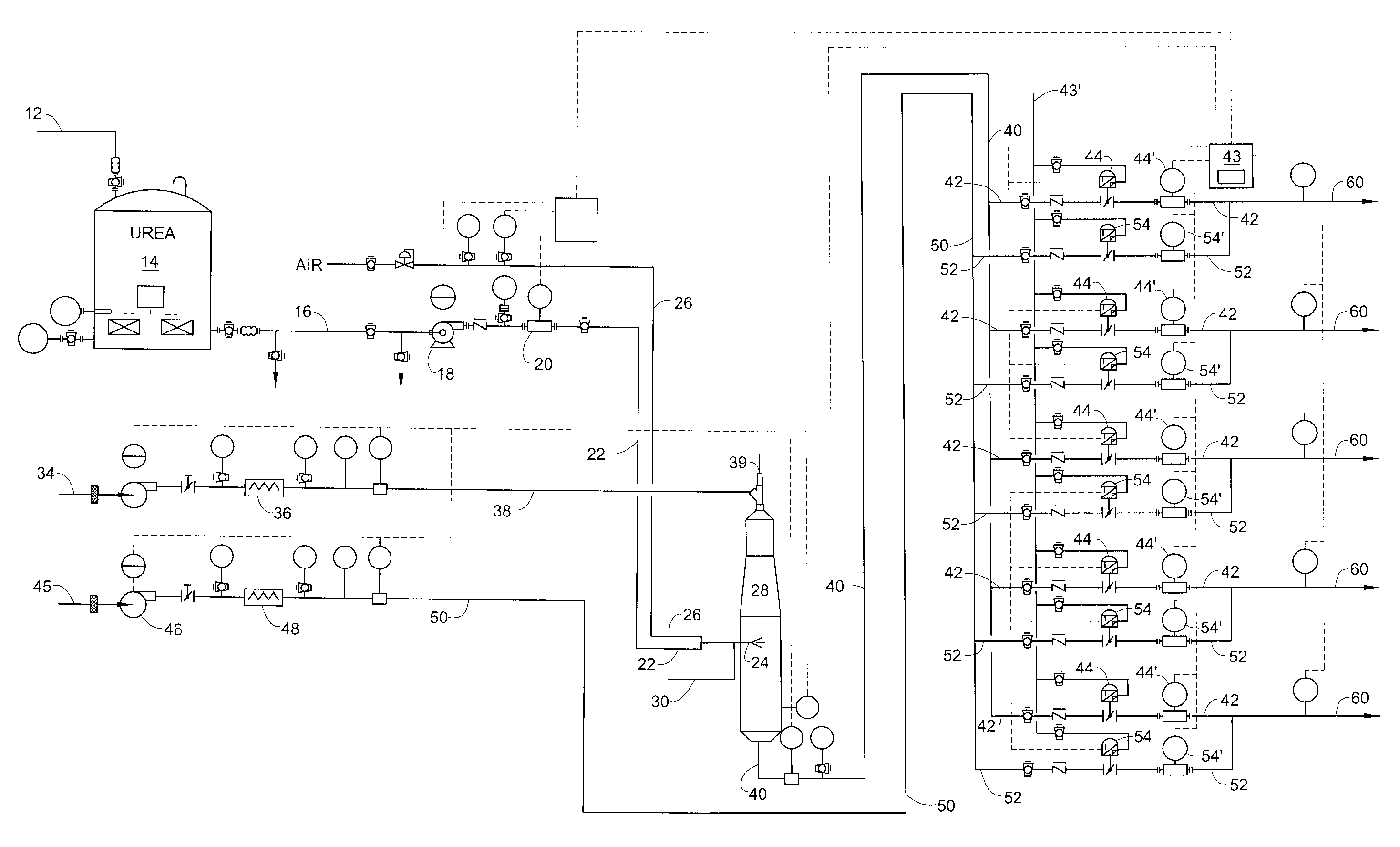
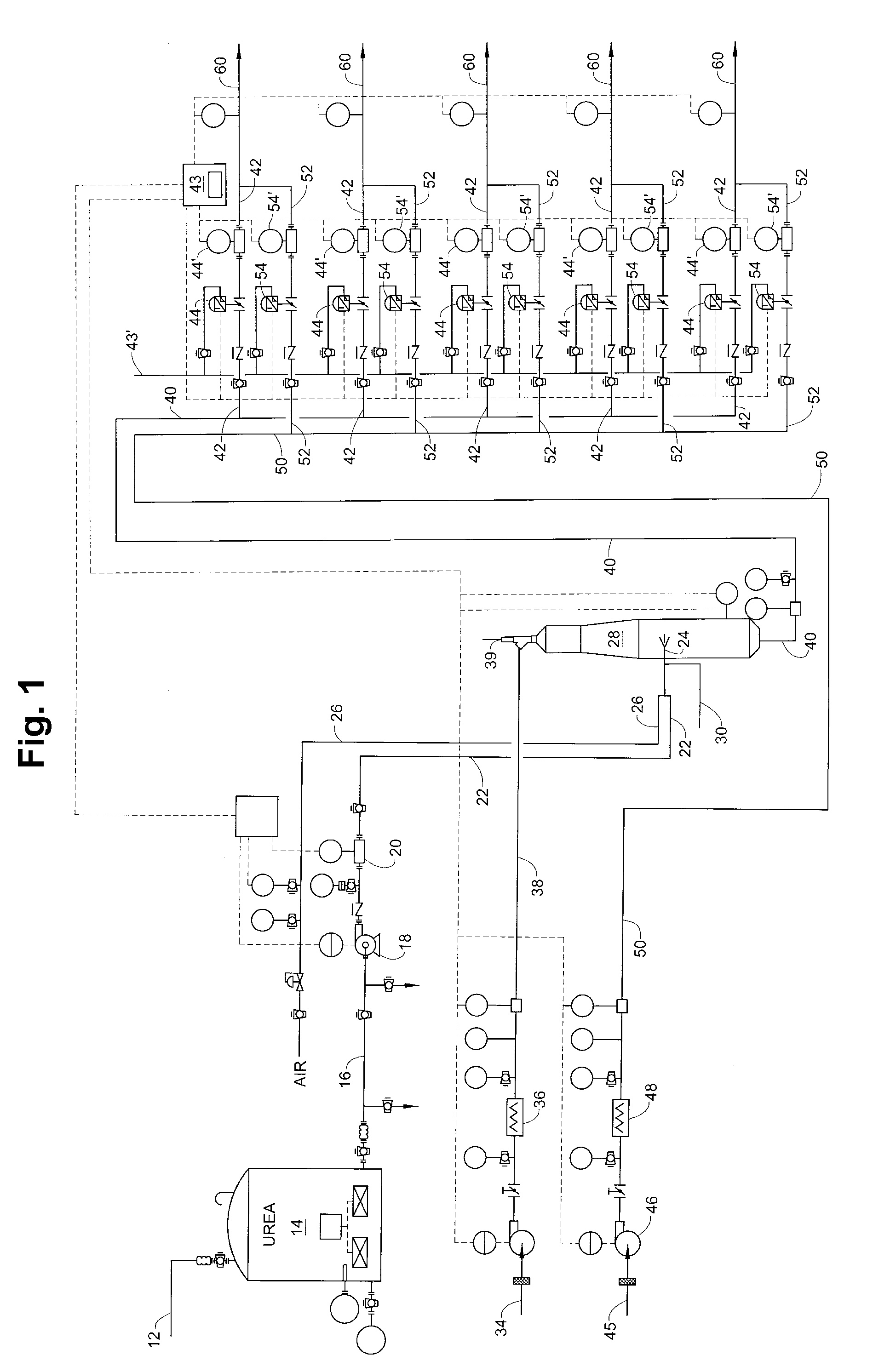
[0017]In describing the present invention, reference is made to the drawings, wherein there is seen a preferred embodiment shown schematically in FIG. 1. The drawing and the process it represents will be described briefly below, without undue recitation of sensors, pumps, indicators, transmitters, valves, pumps, and the like which are so well known to those skilled in engineering systems of this type. Various labels are used in the drawings to have the meanings as follows: TE=temperature element / sensor, LT=level transmitter / sensor, VFD=variable frequency drive, SC=speed control, PI=pressure indicator / sensor, TI=temperature indicator / sensor, FT=flow transmitter, I / P=current to pressure transducer, FIT=flow indicating transmitter, M=flowmeter, PLC=programmable logic controller.

[0018]With reference to FIG. 1, a feed line 12 leads to urea tank 14 to maintain a sufficient supply of an aqueous solution of urea or like chemical as described in U.S. Pat. No. 7,090,810, the disclosure of whi...


PUM


Abstract

Disclosed is a system which enables the efficient utilization of urea for selective catalytic reduction (SCR) of NOx by gasifying it and feeding it to a plurality of selective catalytic reduction units associated with a plurality of gas turbines. The invention enables feeding a gasified product of the urea with the ability to fully control separate SCR units without excessive reagent usage or loss of pollution control effectiveness. Controllers determine the amount of reagent required for each turbine to control NOx emissions and then mixes the gasified urea with the correct amount of carrier gas for efficient operation of each separate SCR unit despite the demand variation between the turbines. In this manner the gasification unit can be properly controlled to provide urea on demand without the need for storing large inventories of ammonia-containing gasses to correct for fluctuations in demand.

Description

RELATED APPLICATION[0001]This application is a continuation of copending U.S. Provisional Application Ser. No. 60,986,917, filed Nov. 9, 2007, the disclosure of which is incorporated herein in its entirety.FIELD OF THE INVENTION[0002]The invention relates generally to the efficient utilization of urea for selective catalytic reduction (SCR) of NOx, and more particularly to feeding a gasified product of the urea to feed multiple turbine power units from a single unit, which converts urea to ammonia-containing SCR reagent yet maintains the ability to fully control separate SCR units without excessive reagent usage or loss of pollution control effectiveness.BACKGROUND OF THE INVENTION[0003]The use of turbines to generate power is economical in many situations where more conventional powerplants cannot be contemplated. To their great credit, they generally operate with minimal generation of NOx and can utilize fuels, such as digester and landfill gases. However, they do generate regulat...

Claims


Application Information

Patent Timeline
IPC IPC(8): B01D53/56
CPCB01D53/8625B01D53/8696F23J2219/10B01D2251/2067F23J15/003B01D53/90B01D53/86B01D53/56
Inventor SUN, WILLIAM H.CARMIGNANI, PAUL G.BOYLE, JOHN M.
Owner FUEL TECH
Why Eureka
Try Eureka