Polymeric coating of substrate processing system components for contamination control

a technology of substrate processing system and contamination control, applied in the direction of superimposed coating process, instruments, synthetic resin layered products, etc., can solve the problems of affecting the performance of devices formed on the substrate surface, so as to reduce the chance of transferring carbon, and reduce the porosity

Inactive Publication Date: 2010-03-25
APPLIED MATERIALS INC
View PDF4 Cites 9 Cited by
  • Summary
  • Abstract
  • Description
  • Claims
  • Application Information

AI Technical Summary

Benefits of technology

[0008]Aspects of the disclosure pertain to a thin coating for metal components used in substrate processing. The thin coatings may comprise nickel (Ni) and a fluoropolymer. The coating may be thinner than dimensional tolerances of the metal components and may adhere more strongly than polymeric coatings to the underlying metal surfaces. The coating may result in a reduced exposed polymer to reduce the chance of transferring carbon to the substrate surface. Another advantage of coatings according t

Problems solved by technology

Substrate processing techniques are sensitive to contamination originating from the interior walls of processing chambers.
The walls of pipes and elements of gas handling systems, gas exhaust systems and pumping systems are also sources of particulates and contaminants which may affect the performance of devices formed on substrate surfaces.
Particulates which migrate to the substrate surface can interfere with the physical formation of vias, lines, transistors, diodes and other features on a substrate surface.
A transfer of contaminants may also result in a change of dopant concentration or metal contamination which can adversely affect the performance of transistors and diodes by altering, even slightly, the chemical compos

Method used


Image

  • Polymeric coating of substrate processing system components for contamination control
  • Polymeric coating of substrate processing system components for contamination control
  • Polymeric coating of substrate processing system components for contamination control

Examples


Embodiment Construction

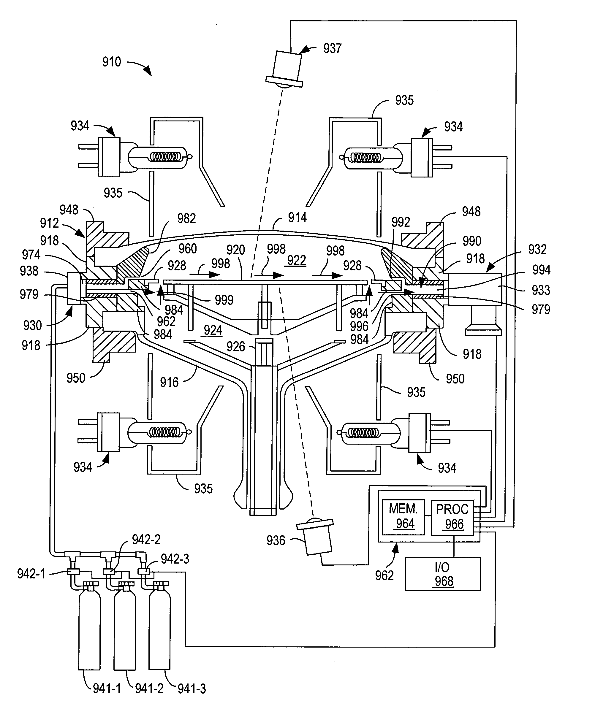
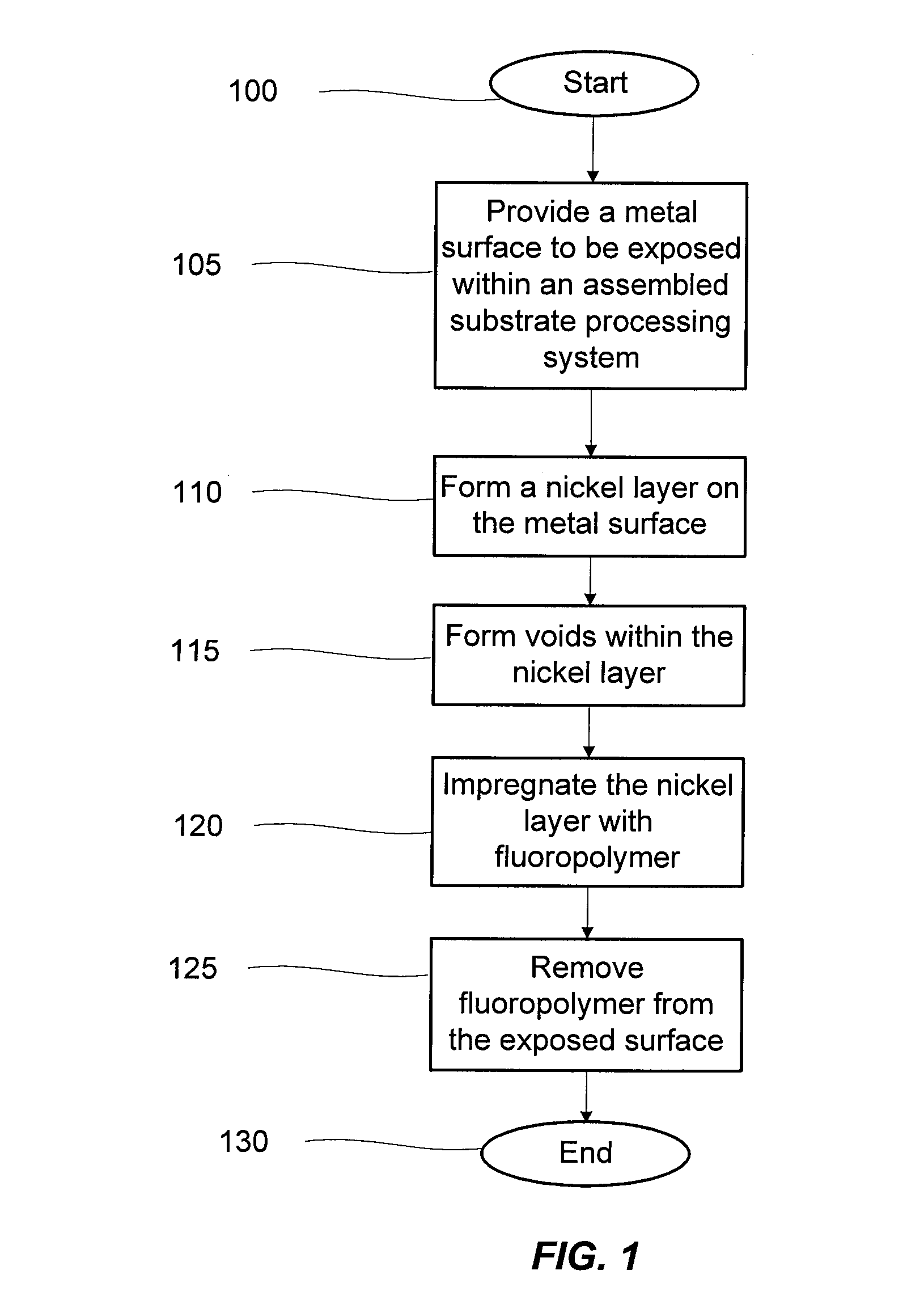
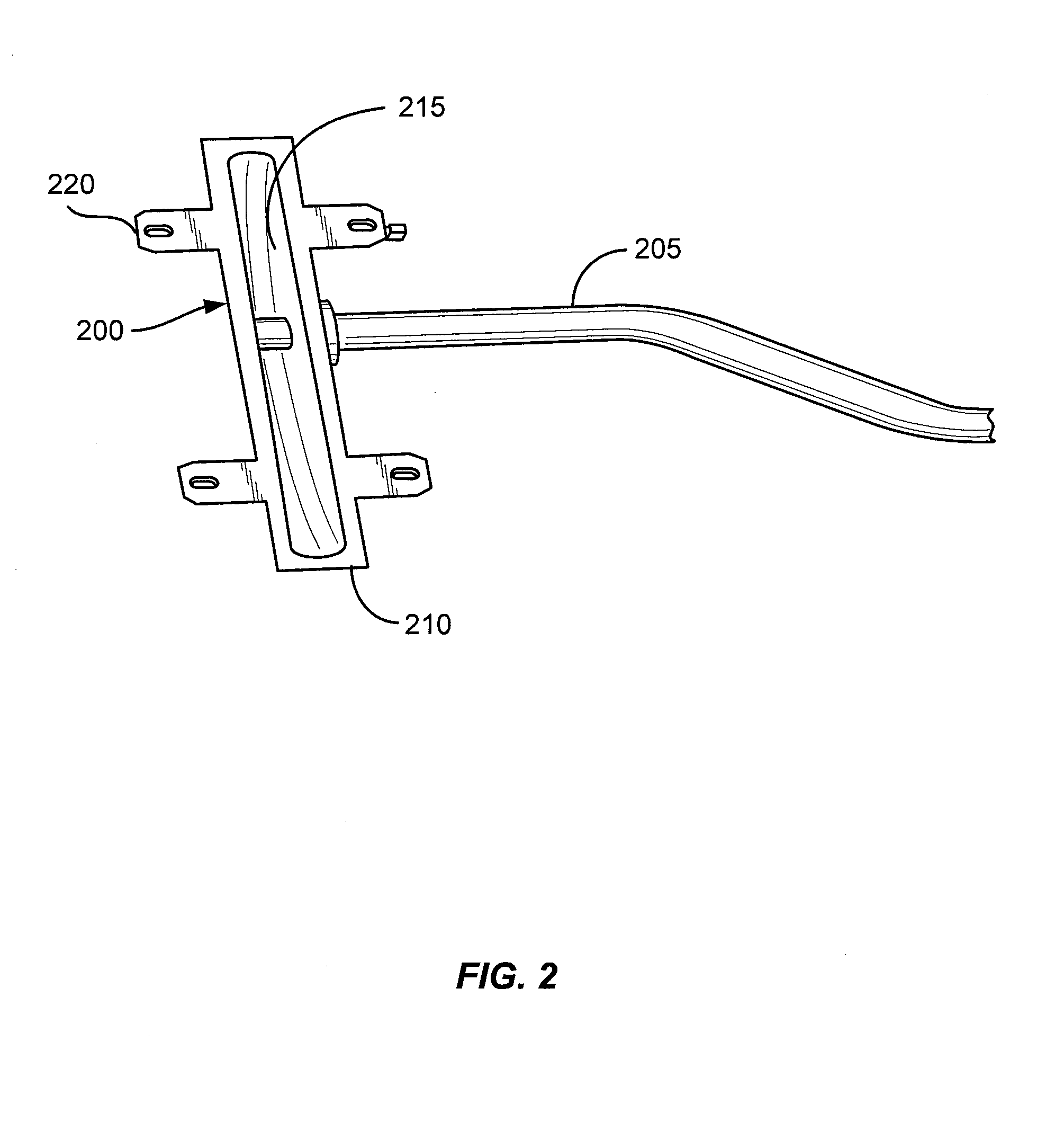
[0022]Aspects of the disclosure pertain to thin protective coatings (and their methods of deposition) for metal components used in substrate processing. The coatings may comprise nickel (Ni) and fluoropolymer and may be thinner than dimensional tolerances of the metal components. The coatings may also adhere to the underlying metal surfaces more strongly than common polymeric coatings. The coatings may possess a reduced exposed polymer to reduce the chance of transferring carbon to the substrate surface. Other advantages of the coatings are a reduced porosity, which reduces the potential for gases to penetrate through the film and compromising the physical integrity of the coating-metal interface. Coatings may exhibit a very smooth surface to slow the accumulation of deposits on the interior walls of chamber components and may be hydrophobic to limit or slow the absorption of water during cleaning procedures. Additional benefits include a high lubricity, which is helpful in regions ...


PUM

PropertyMeasurementUnit
Thicknessaaaaaaaaaa
Thicknessaaaaaaaaaa
Thicknessaaaaaaaaaa

Abstract

A method of treating a metal surface of a portion of a substrate processing system to lower a defect concentration near a processed surface of a substrate includes forming a protective coating on the metal surface, wherein the protective coating includes nickel (Ni) and a fluoropolymer. Forming the protective coating on the metal surface can further include forming a nickel layer on the metal surface, impregnating the nickel layer with a fluoropolymer, and removing fluoropolymer from the surface leaving a predominantly nickel surface so the fluoropolymer is predominantly subsurface. A substrate processing system includes a process chamber into which a reactant gas is introduced, a pumping system for removing material from the process chamber, a first component with a protective coating, wherein the protective coating forms a surface of the component which is exposed to an interior of the substrate processing chamber or an interior of the pumping system. The protective coating includes nickel (Ni) and a flouropolymer.

Description

CROSS REFERENCE TO RELATED APPLICATIONS[0001]This application is related to International Application No. PCT / JP00 / 03410 titled “Apparatus for manufacturing semiconductor device,” by Kazuyoshi Saito et al., which was published on Dec. 7, 2000 as International Publication No. WO 00 / 74125 A1, the content of which is incorporated herein by reference in its entirety.BACKGROUND[0002]This application relates to substrate processing equipment including semiconductor manufacturing equipment, display panel manufacturing equipment and solar panel manufacturing equipment. More particularly, the application relates to improving defect levels of substrate processing equipment.[0003]Substrate processing techniques are sensitive to contamination originating from the interior walls of processing chambers. The walls of pipes and elements of gas handling systems, gas exhaust systems and pumping systems are also sources of particulates and contaminants which may affect the performance of devices forme...

Claims


Application Information

Patent Timeline
IPC IPC(8): B05D5/00B32B27/04B32B9/00
CPCB05D5/083B05D7/14B05D2350/65C23C2/26C23C26/00Y10T428/265C23C30/00Y10T428/263Y10T428/239Y10T428/264C23C28/00Y10T428/3154
Inventor CARLSON, DAVID K.ANDERSON, ROGER N.
Owner APPLIED MATERIALS INC
Why Eureka
Try Eureka