

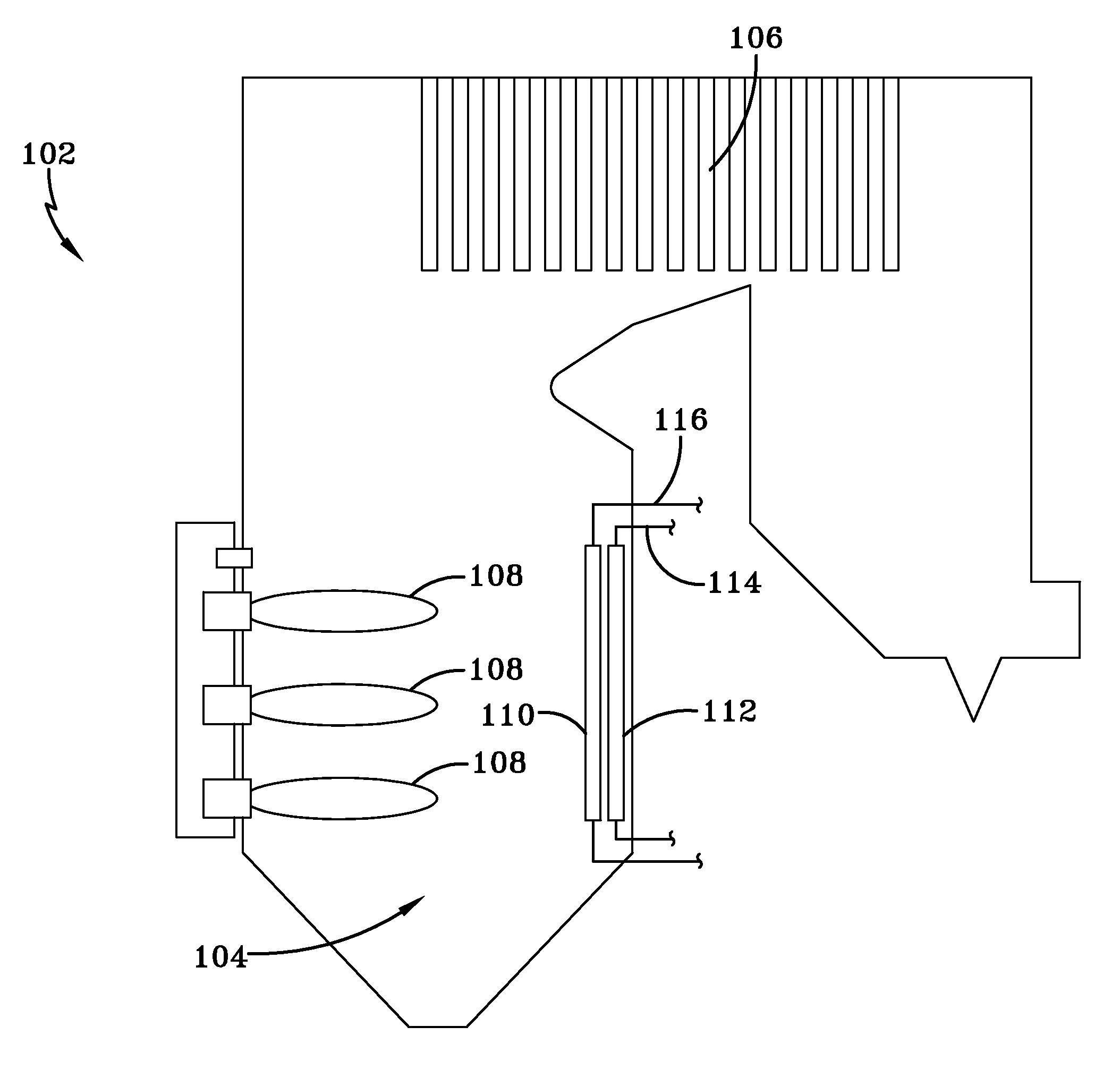
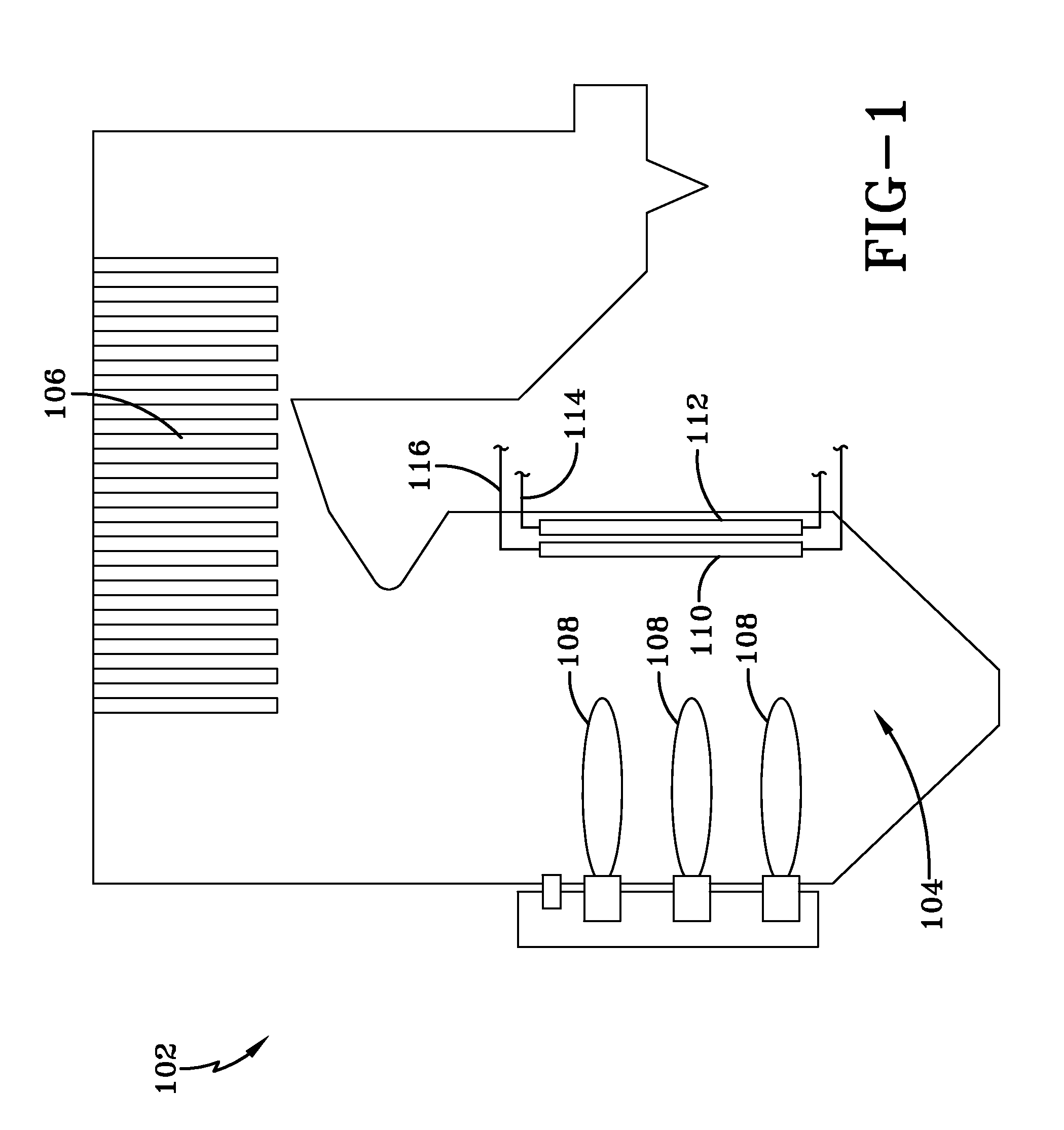
Oxy/fuel combustion system having combined convective section and radiant section
a combustion system and convective section technology, applied in indirect heat exchangers, fire-box steam boilers, lighting and heating apparatus, etc., can solve the problems of unprotected steam tubes exposed to high heat fluxes, inability to accept heat fluxes, and known systems that do not provide protection for superheat tubes, etc., to achieve the effect of reducing the overall cos
- Summary
- Abstract
- Description
- Claims
- Application Information
AI Technical Summary
Benefits of technology
Problems solved by technology
Method used
Image

Examples
examples
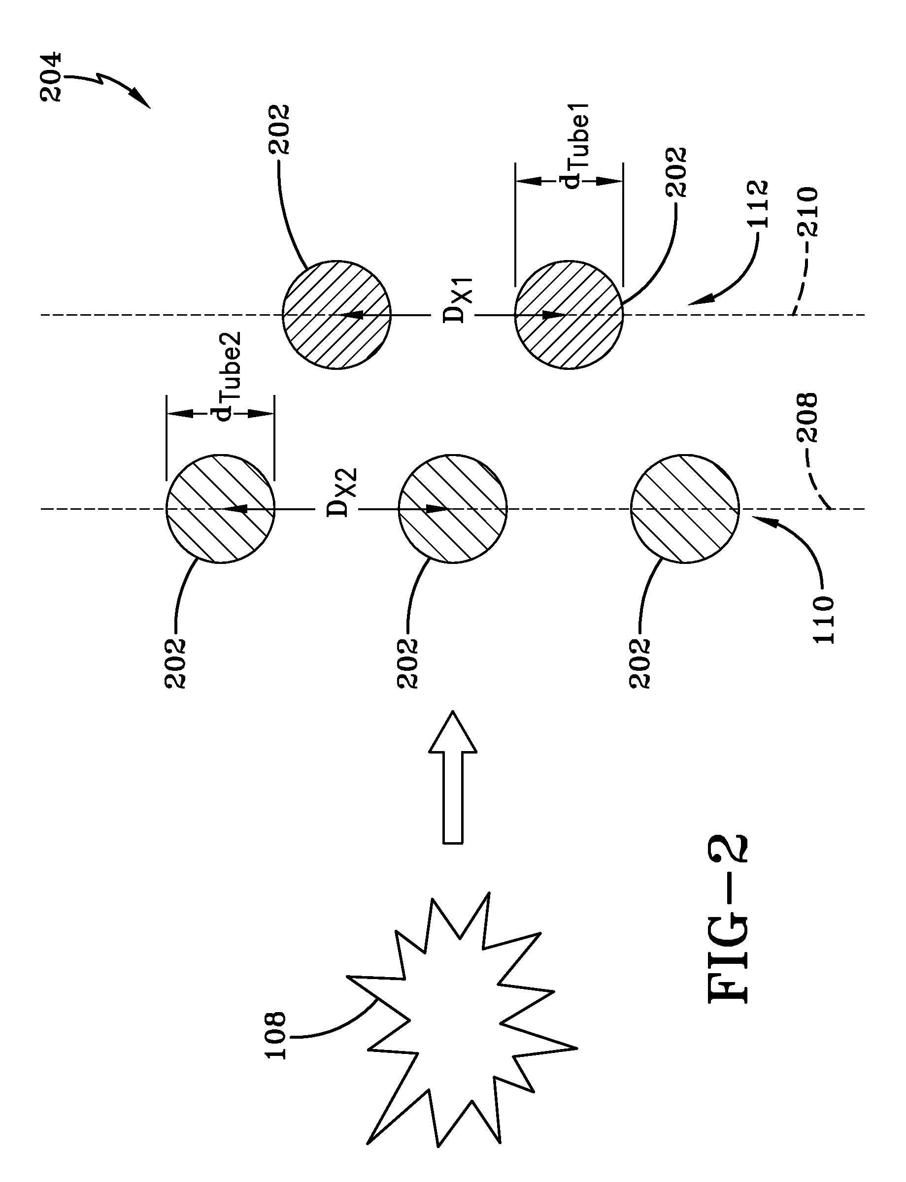
[0056]An example of the current disclosure was studied using computational fluid dynamics (CFD) simulating temperature distribution and heat transfer. The simulation region consists of a 2D rectangular area. One wall boundary was assumed to be at 3140° F. (2000 K) to mimic hot furnace gases. This boundary temperature was chosen to ensure that the maximum heat flux to the water tube was less than the critical heat flux for water. A mixed boundary condition (convection plus radiation) was applied at the opposite boundary which was assumed to be made of a 1 ft thick refractory brick. A periodic boundary condition was applied at the adjacent sides of the simulation area (see e.g., FIG. 15). The water tubes (i.e. the thermal shield 110) and steam tubes (i.e., the first heat exchanger 112) were 2 inches in outer diameter with a wall thickness of 0.375 inches (0.95 cm). The conductivity of the metal tubes varied with temperature and was assumed to be the same as stainless steel. Both the w...
PUM
 Abstract
Description
Claims
Application Information