Method and arrangement for the operation of plasma-based short-wavelength radiation sources

a short-wavelength radiation source and plasma technology, applied in the direction of radiation therapy, x-ray tube with very high current, therapy, etc., can solve the problems of adversely affecting the plasma (or its development), difficult to realize high-pressure gradients, and damage to these components, so as to achieve the effect of extensive debris mitigation

Inactive Publication Date: 2010-04-01
XTREME TECH
View PDF12 Cites 15 Cited by
  • Summary
  • Abstract
  • Description
  • Claims
  • Application Information

AI Technical Summary

Benefits of technology

[0018]It is the object of the invention to find a novel possibility for operating plasma-based short-wavelength radiation sources with a long lifetime which permits extensive debris mitigation without the...

Problems solved by technology

As a result of their impact upon surfaces of adjacent components (electrodes, optics, sensors, etc.), these high-energy particles cause a removal of material (sputtering) leading to considerable damage to these components in the course of continuous operation of the radiation source.
On the one hand, the high pressure can adversely affect the plasma (or its development, primarily in gas discharge sources).
This results in large apertures even at a short distance from the plasma, between which it is very difficult to realize high pressure gradients for spatially limiting a region of high gas pressure.
The emitter elements themselves are not suitable as buffer gases because they are either not gases (Sn, Li) and/or their absorption cross section for EUV radiation is too high (Xe, Sn, Li).
In gas discharge-based plasma radiation sources, it is not even possible to prevent the buffer gas from being directly excited by the electrical current of the discharge.
In such cases, unwanted effects are brought abou...

Method used


Image

  • Method and arrangement for the operation of plasma-based short-wavelength radiation sources
  • Method and arrangement for the operation of plasma-based short-wavelength radiation sources
  • Method and arrangement for the operation of plasma-based short-wavelength radiation sources

Examples


Embodiment Construction

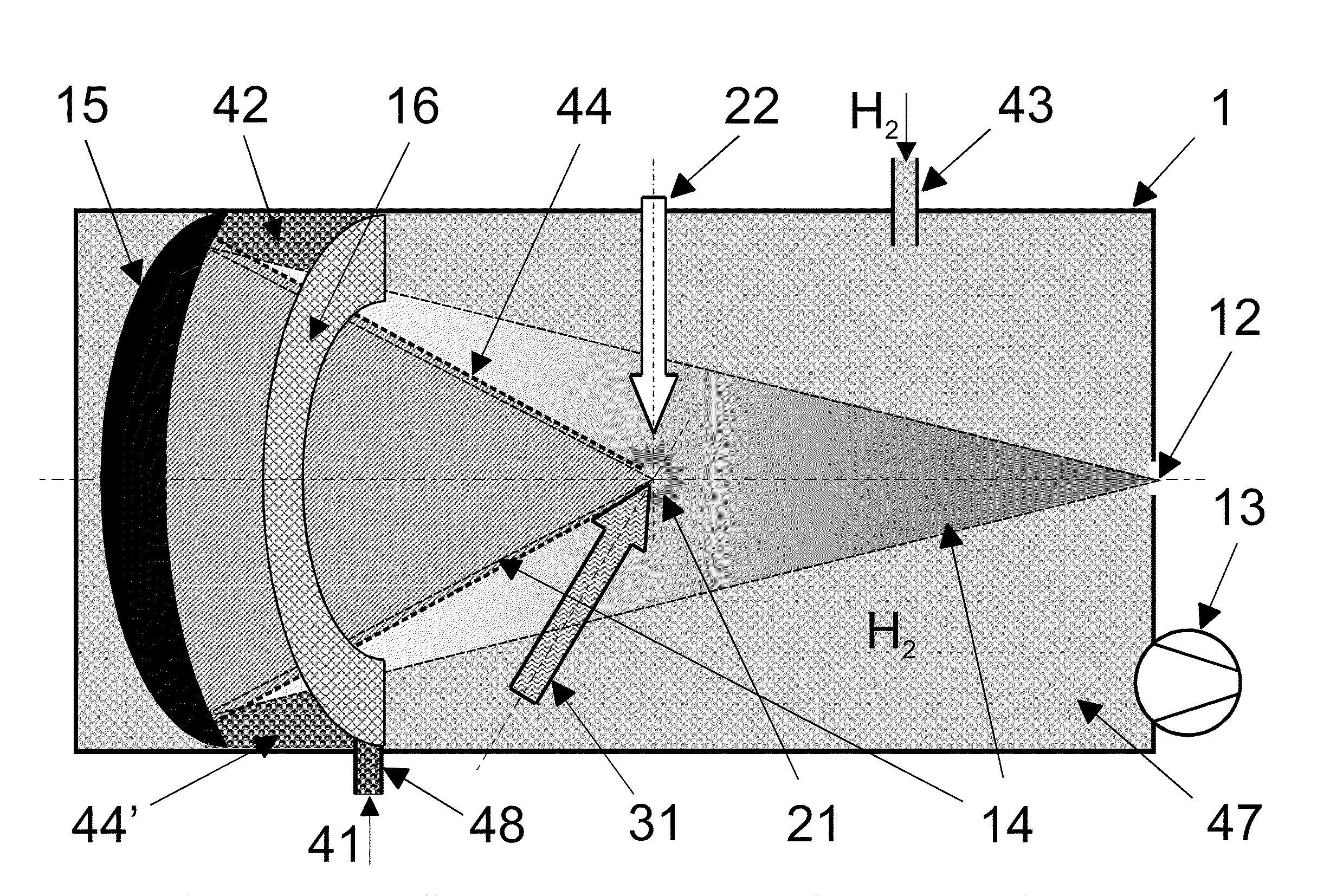
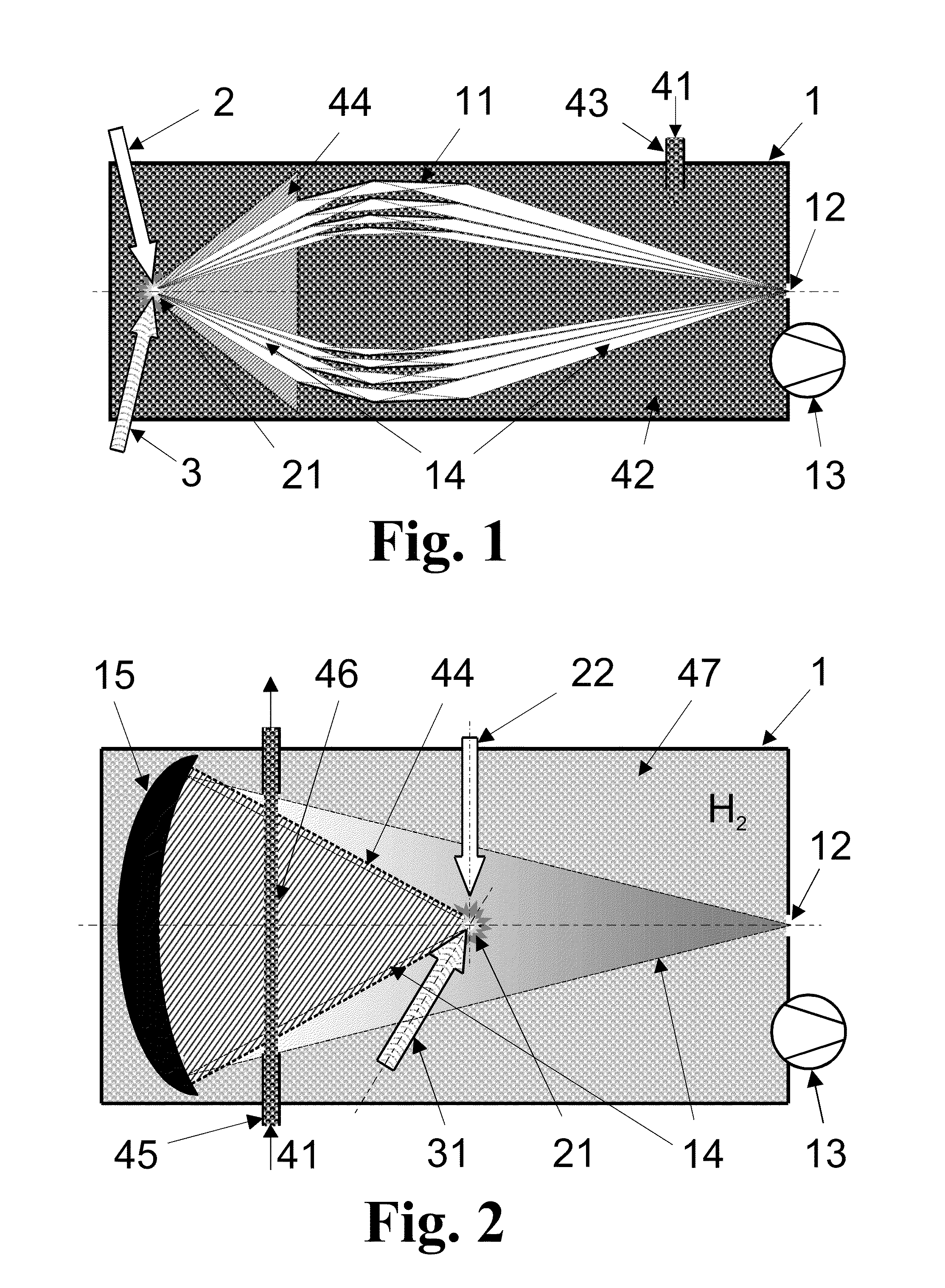
[0048]The method according to the invention for operating a plasma-based short-wavelength radiation source with a high lifetime has the following steps:

[0049]an emitter material with a high emission efficiency in the desired wavelength range is supplied in a metered manner in a vacuum chamber for generating an emitter plasma;

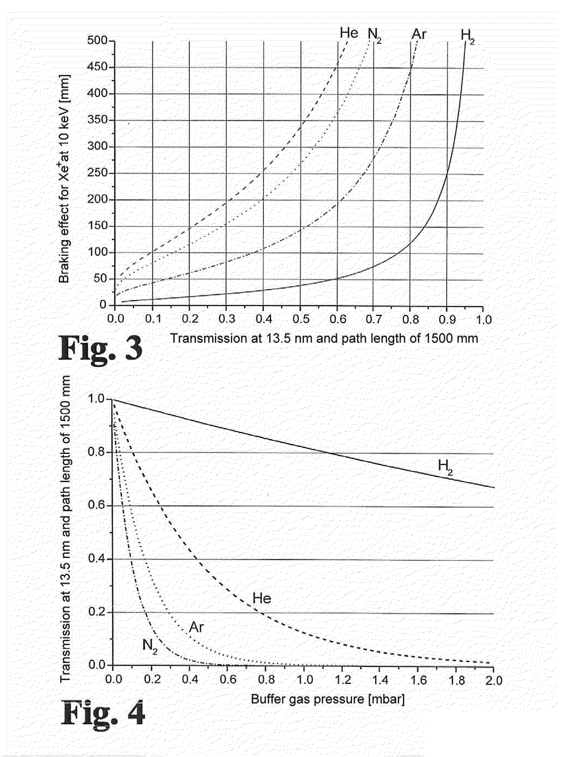
[0050]hydrogen gas is introduced as buffer gas with a pressure-distance product in the range of 1 to 100 Pa·m;

[0051]a spatially narrowly limited hot emitter plasma is generated by a directed energy feed;

[0052]fast particles of emitter material are slowed down below a defined energy level (so-called sputter threshold) by impacts in the buffer gas;

[0053]the short-wavelength radiation exiting divergently from the emitter plasma is bundled by means of a collector in an intermediate focus;

[0054]the vacuum chamber is continuously suctioned out for quasistatic adjustment of pressure in the vacuum chamber and for removing excess emitter material and buffer gas.

[0055]At ...


PUM


Abstract

The invention is directed to a method for operating plasma-based short-wavelength radiation sources, particularly EUV radiation sources, having a long lifetime and to an arrangement for generating plasma-based short-wavelength radiation. It is the object of the invention to find a novel possibility for operating plasma-based short-wavelength radiation sources with a long lifetime which permits extensive debris mitigation without the main process of radiation generation being severely impaired through the use of buffer gas and without the need for substantial additional expenditure for generating partial pressure in a spatially narrowly limited manner. According to the invention, this object is met in that hydrogen gas as buffer gas (41) is introduced into the vacuum chamber (1) under a pressure such that a pressure-distance product in the range of 1 to 100 Pa·m is realized while taking into account the geometric radiation paths of the radiation emitted by the emitter plasma (21) within the buffer gas (41; 44), and the vacuum chamber (1) is continuously evacuated for adjusting a quasistatic pressure (42; 47) and for removing residual emitter material and buffer gas (41).

Description

RELATED APPLICATIONS[0001]This application claims priority to German Patent Application No. 10 2008 049 494.1, filed Sep. 27, 2008, which is incorporated herein by reference in its entirety.FIELD OF THE INVENTION[0002]The invention is directed to a method and an arrangement for the operation of plasma-based short-wavelength radiation sources, particularly EUV radiation sources, having a long lifetime. The invention is preferably applied in radiation sources for semiconductor lithography.BACKGROUND OF THE INVENTION[0003]As per the state of the art, there are currently two basic concepts that are considered promising for EUV lithography: Laser-Produced Plasma (LPP) radiation sources and Gas Discharge Plasma (GDP) radiation sources.[0004]In both concepts, an emitter element (typically Xe, Sn or Li, or chemical compounds formed therefrom) is excited by laser radiation or electrical current to form a hot plasma which then emits radiation with a high proportion in the desired wavelength r...

Claims


Application Information

Patent Timeline
IPC IPC(8): G21K5/00
CPCG03F7/70033H05G2/003G03F7/70916G03F7/70841
Inventor SCHUERMANN, MAX CHRISTIANTKACHENKO, BORISBOLSHUKHIN, DENISKLEINSCHMIDT, JUERGENSCHRIEVER, GUIDO
Owner XTREME TECH
Why Eureka
Try Eureka