Method for introducing a catalytic coating into the pores of a ceramic honeycomb flow body

a technology of ceramic honeycomb and catalytic coating, which is applied in the direction of physical/chemical process catalysts, metal/metal-oxide/metal-hydroxide catalysts, and separation processes, etc., can solve the problems of increasing the amount of catalyst deposited on the honeycomb body to only a small extent, and achieves the effect of increasing the banking-up pressure through the honeycomb body

Active Publication Date: 2010-04-15
UMICORE AG & CO KG
View PDF11 Cites 36 Cited by
  • Summary
  • Abstract
  • Description
  • Claims
  • Application Information

AI Technical Summary

Benefits of technology

[0013]It is an object of the present invention to provide a process for coating porous honeycomb bodies, which allows both the exterior surfaces of the flow channels and the pores of the channel walls to be coated with a catalyst. In this way, it should be possible to coat the honeycomb bodies with a larger amount of catalyst material than would be possible by conventional processes, without the banking-up pressure through the honeycomb body being increased.

Problems solved by technology

In addition, high layer thicknesses reduce the hydraulic diameter of the flow channels and thus increase the counter pressure of the exhaust gas (banking-up pressure) through the catalyst.
However, this increases the amount of catalyst deposited on the honeycomb body to only a small extent.

Method used


Image

  • Method for introducing a catalytic coating into the pores of a ceramic honeycomb flow body
  • Method for introducing a catalytic coating into the pores of a ceramic honeycomb flow body
  • Method for introducing a catalytic coating into the pores of a ceramic honeycomb flow body

Examples


example

[0053]A further honeycomb body having the same properties as in the comparative example was coated with the catalyst suspension of the comparative example by the process of the invention.

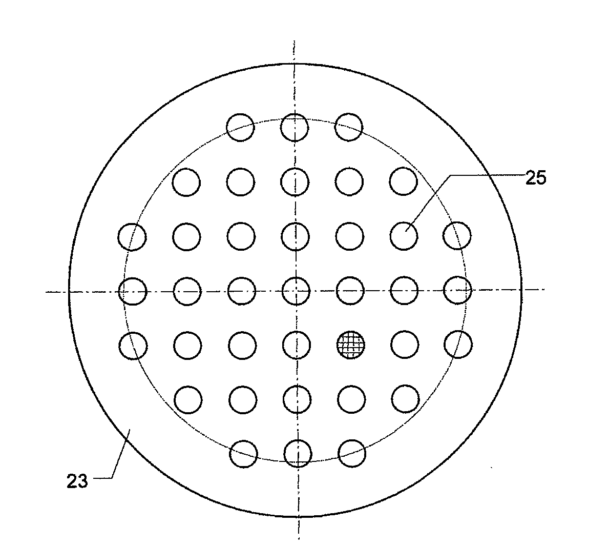
[0054]As perforated mask for the lower end face, use was made of a perforated mask having holes as shown in FIG. 3. The holes (25) had a diameter of 6 mm and were arranged in a square grid having a grid spacing of 12 mm. The diameter of the honeycomb body is indicated by the circle shown as a dotted line. The grid of the flow channels of the honeycomb body is indicated in one hole of the perforated mask. The holes selected for the perforated mask cover about 18 flow channels.

[0055]As perforated mask for the upper end face, use was made of a perforated mask having holes as shown in FIG. 4. The holes of this mask had a diameter of 3 mm.

[0056]After calcination, the honeycomb body was coated with 20% more solids than the honeycomb body of the comparative example. The banking-up pressure of this honeycom...


PUM

PropertyMeasurementUnit
pore diameteraaaaaaaaaa
porosityaaaaaaaaaa
particle size d50aaaaaaaaaa

Abstract

The invention relates to a process for coating ceramic honeycomb bodies with a catalyst suspension comprising catalyst components as solids and/or in dissolved form in a carrier liquid. Parallel flow channels run through the honeycomb bodies. The walls of the flow channels have an open pore structure. To coat the channel walls and in particular also the interior surfaces of the pores with the catalyst suspension, the entry and exit end faces of the vertically aligned honeycomb bodies are each brought into contact with a perforated mask, with the perforated masks being arranged so that the open regions of the perforated mask on the one end face are opposite the closed regions of the perforated mask on the other end face and vice versa. The catalyst suspension is then pumped or sucked from below into the honeycomb bodies until it exits at the upper end face. Excess suspension is then removed by blowing-out or sucking-out, the contact with the perforated masks is released and the honeycomb body is calcined to fix the coating.

Description

[0001]The invention relates to a process by means of which a catalytic coating can be introduced into the pores of a ceramic flow-through honeycomb body using a catalyst suspension comprising catalyst components as solids and / or in dissolved form in a carrier liquid. The coated honeycomb bodies are preferably used for the purification of automobile exhaust gases.[0002]Catalysts applied in the form of a coating to honeycomb bodies have for decades been used for the purification of automobile exhaust gases. Parallel flow channels for the exhaust gases run through the honeycomb bodies. Ceramic honeycomb bodies are produced from refractory materials. The material is predominantly cordierite, a magnesium-aluminum silicate. Further customary ceramic materials are silicon carbide, aluminum oxide, zirconium oxide, zirconia-mullite, mullite, silicon nitride, aluminum titanate and titanium oxide. The honeycomb bodies are produced from these materials by extrusion and generally have an open po...

Claims


Application Information

Patent Timeline
Patent Type & Authority Applications(United States)
IPC IPC(8): B01J23/42
CPCB01J23/42B01J35/04B05D7/22B01J37/0248B05D3/042B01J37/0215B01D46/24B01D53/94B01J37/02
Inventor HASSELMANN, WOLFGANG
Owner UMICORE AG & CO KG
Why Eureka
Try Eureka