
Solid state imaging device and fabrication method for the same

a solid-state imaging and fabrication method technology, applied in semiconductor/solid-state device manufacturing, semiconductor devices, electrical devices, etc., can solve the problem of 400 degree c heat resistance limitation of integrated circuits, and achieve the effect of preventing leakage current generation and reducing dark current at the pn junction interfa

Inactive Publication Date: 2010-04-29
NAT INST OF ADVANCED IND SCI & TECH
View PDF4 Cites 40 Cited by
  • Summary
  • Abstract
  • Description
  • Claims
  • Application Information

AI Technical Summary

Benefits of technology

[0012]According to this configuration, the solid state imaging device, with an easy structure, having the optical absorption sensitivity of the compound semiconductor thin film of chalcopyrite structure can be obtained.
[0020]According to this configuration, the solid state imaging device, with an easy structure, in which provides the optical absorption sensitivity of the compound semiconductor thin film of chalcopyrite structure, and which does not need patterning the optical transparent electrode layer can be obtained.
[0022]According to this configuration, the widening of bandgap energy of the CIS based thin film (CuInSe2) becomes effective by using the CIGS based thin film which displaced a part of In (indium) to gallium. Accordingly, by expanding the bandwidth, the recombination processing of carriers can be reduced and reduction of dark current can be achieved.
[0024]According to this configuration, the void and the pinhole which are produced in the CIGS thin film of the underlying are embedded by a semi-insulating layer by providing a non-doped ZnO film (i-ZnO) as the optical transparent electrode layer, and the generation of leakage current can be prevented.

Problems solved by technology

In addition, the heat-resistant limitation of an integrated circuit is about 400 degrees C.

Method used


Image

  • Solid state imaging device and fabrication method for the same
  • Solid state imaging device and fabrication method for the same
  • Solid state imaging device and fabrication method for the same

Examples


first embodiment

Modified Example of First Embodiment

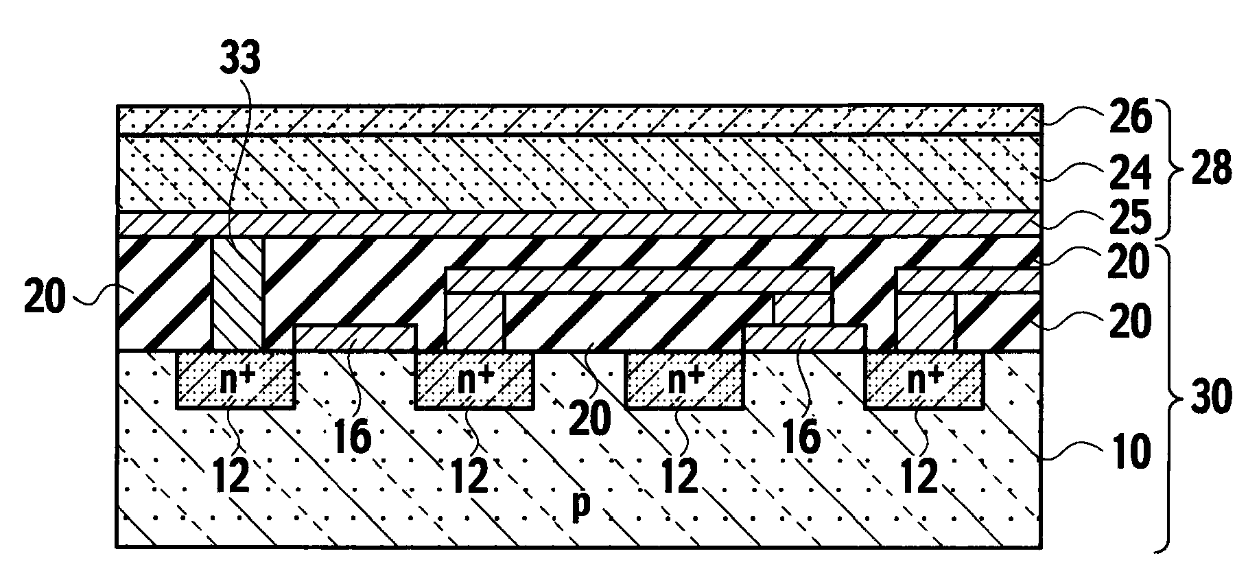
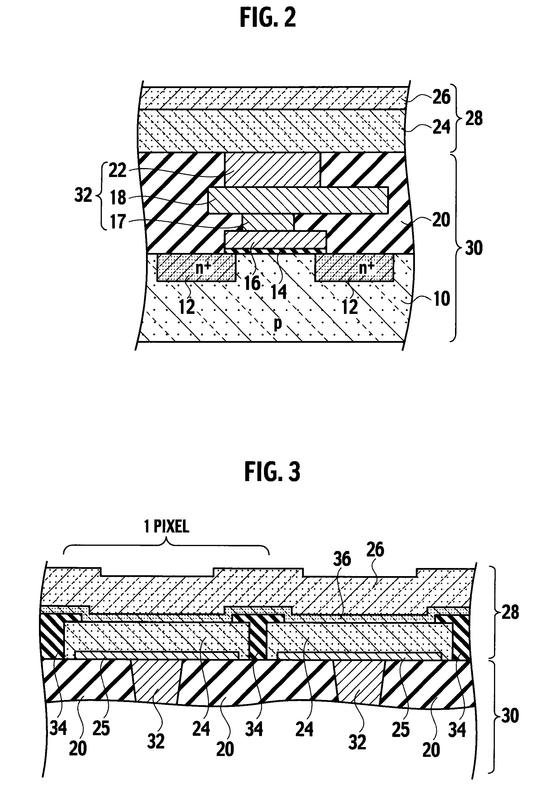
[0124]As shown in FIG. 13 as a cross-sectional view of one pixel part, a solid state imaging device according to amodified example of the first embodiment of the present invention includes: a circuit unit 30 formed on the semiconductor substrate 10; and a photoelectric conversion unit 28 including a lower electrode layer 25 placed on the circuit unit 30, a compound semiconductor thin film (Cu(Inx, Ga1−x)Se2 (where 024 of chalcopyrite structure which is placed on the lower electrode layer 25 and functions as an optical absorption layer, and an optical transparent electrode layer 26 placed on the compound semiconductor thin film 24.

[0125]The lower electrode layer 25, the compound semiconductor thin film 24, and the optical transparent electrode layer 26 are laminated one after another on the circuit unit 30.

[0126]Moreover, the circuit unit 30 includes a transistor by which the lower electrode layer 25 is connected to a gate electrode 16, in the soli...

second embodiment

Modified Example of Second Embodiment

[0149]As shown in FIG. 15 as a cross-sectional view of one pixel part, a solid state imaging device according to the modified example of the second embodiment of the present invention includes: a circuit unit 30 formed on a semiconductor substrate 10; and a photoelectric conversion unit 28 including a lower electrode layer 25 placed on the circuit unit 30, a compound semiconductor thin film (Cu(Inx, Ga1−x)Se2 (where 024 of chalcopyrite structure which is placed on the lower electrode layer 25 and functions as an optical absorption layer, and an optical transparent electrode layer 26 placed on the compound semiconductor thin film 24.

[0150]The lower electrode layer 25, the compound semiconductor thin film 24, and the optical transparent electrode layer 26 are laminated one after another on the circuit unit 30.

[0151]The circuit unit 30 includes a transistor by which the lower electrode layer 25 is connected to the source / drain region 12, in the soli...


PUM


Abstract

A solid state imaging device with an easy structure in which have the high sensitivity which reaches the wide wavelength region from visible light to near infrared light wavelength region, and dark current is reduced, and a fabrication method for the same, are provided.A solid state imaging device and a fabrication method for the same, the solid state imaging device comprising: a circuit unit (30) formed on a substrate; and a photoelectric conversion unit (28) including a lower electrode layer (25) placed on the circuit unit (30), a compound semiconductor thin film (24) of chalcopyrite structure which is placed on the lower electrode layer (25) and functions as an optical absorption layer, and an optical transparent electrode layer (26) placed on the compound semiconductor thin film (24), wherein the lower electrode layer (25), the compound semiconductor thin film (24), and the optical transparent electrode layer (26) are laminated one after another on the circuit unit (30).

Description

TECHNICAL FIELD[0001]The present invention relates to a solid state imaging device and a fabrication method for the same. In particular, the present invention relates to a solid state imaging device provided with a compound semiconductor film of a chalcopyrite structure composed of Cu(In, Ga)Se2 in a photoelectric conversion unit, and a fabrication method for the same.BACKGROUND ART[0002]The thin film solar cell using CuInSe2 (CIS based thin film) which is the semiconductor thin film of chalcopyrite structure composed of a group Ib element, a group IIIb element, and a group IVb element, or Cu(In, Ga)Se2 (CIGS based thin film) which dissolves Ga to this, for an optical absorption layer, has an advantage that high energy conversion efficiency is indicated and there is little degradation of the efficiency according to light irradiation etc.[0003]However, film formation by 550 degrees C. from a viewpoint of deterioration of film quality and increase of leakage current is general, in for...

Claims


Application Information

Patent Timeline
Patent Type & Authority Applications(United States)
IPC IPC(8): H01L31/032H01L31/18H04N25/00
CPCH01L27/14632H01L27/14687H01L27/14665H01L31/18H01L31/0322
Inventor MATSUSHIMA, OSAMUTAKAOKA, MASAKIMIYAZAKI, KENICHIISHIZUKA, SHOGOSAKURAI, KEIICHIRONIKI, SHIGERU
Owner NAT INST OF ADVANCED IND SCI & TECH
Learn More