The potential for airport and
runway collisions increases as a function of the frequency of landing and
takeoff.
In other words, the busier the airport, the greater is the likelihood of
runway intrusions.
But there are many other sources of collision that appear not to be handled by U.S. Pat. No. 6,246,320.
Likewise, an aircraft that is taking off or landing at high speed may be too fast for the GPS
system employed by U.S. Pat. No. 6,246,320 to respond in
sufficient time to allow evasive action to be taken.
In any event, the
system disclosed in U.S. Pat. No. 6,246,320 is not capable of permitting collision avoidance in crowded airport environments, for a number of reasons.
First, the large high and increasing volume number of takeoffs and landings may be expected to give rise to a statistical increase in the number of collisions.
At the same time, the increased volume adds to the pressure on pilots, which may be expected to increase still further the risk of collision.
These conditions do not obtain in crowded airports with frequent takeoffs and landings on a restricted number of runways.
As noted above, an aircraft that is taking off or landing at high speed may be too fast to allow know systems to respond in sufficient time to allow evasive action to be taken.
When two or more satellites are employed that are spatially separated by very large distances, it is not possible to synchronize in the
time domain to both satellites simultaneously.
However the same temporal alignment does not hold when the uplink signals arrive at the second satellite owing to the spatial separation between the two satellites that gives rise to
time delays between signals arriving from the mobile units to the different satellites.
The problem becomes challenging owing to the large relative
delay between users arising from large geographical variance.
If the guard-interval is too large, this prevents collisions but reduces the average
transmission rate.
However, in the case where the relative
delay exceeds the guard-interval, which may be approximately 50 microseconds, inter-symbol interference will occur.
This imposes practical limitations when
WiMAX is used for an aircraft anti-
collision system since particularly during landing and
takeoff when aircraft are traveling at high speeds, there is a higher risk of data collisions and vital data can therefore be lost during the crucial fractions of a second when warning and evasive action would still be possible if data arrived intact.
However, even when aircraft are confined to the relative proximity of the airport and are thus able to communicate without the need for satellite links, their high speeds give rise to
Doppler frequency shifts.
Problems of Doppler shift are particularly acute when high speed aircraft take off and come in to land.
Specifically, the high velocities associated with an aircraft anti-
collision system imply
Doppler frequency shifts exceeding the customary values of mobile
WiMAX (usually up to 400 Hz), which means that the standard
WiMAX frequency synchronization mechanism is unsuitable.
Usually frequency offsets results from
clock mismatch (the
clock of the
base station vs. that of the mobile platform) and Doppler shifts induced by motion.
However, in the case of Doppler, the uplink
signal propagating from the mobile platform to the
base station experiences another Doppler shift (similar to the downlink
signal) which is not compensated for by the mobile platform.
However in the case of significantly larger velocities (or significantly larger carrier frequencies), the Doppler shift causes larger inter-carrier-interference which may considerably degrade the system performance.
However, the
radar does not tag aircraft—in other words, each blip on the screen does not have an attached information tag that identifies the aircraft, nor does it contain any conflict prediction or alerting logic.
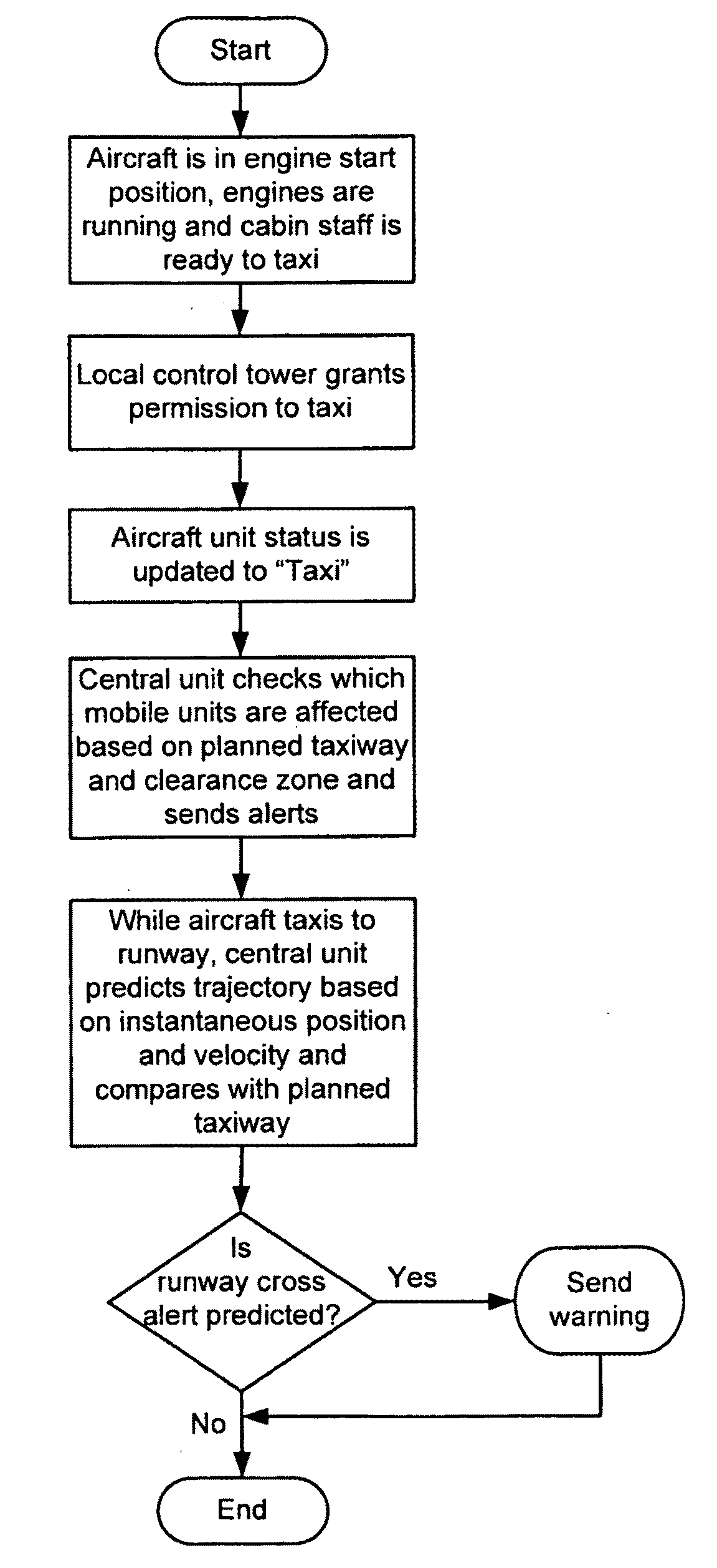
Currently, pilots use paper maps to navigate the airport surface, and can become disoriented, leading to
runway incursions.
In fact, loss of situational awareness is thought to be the most common cause of
pilot deviations, which are themselves the most common cause of runway incursions.
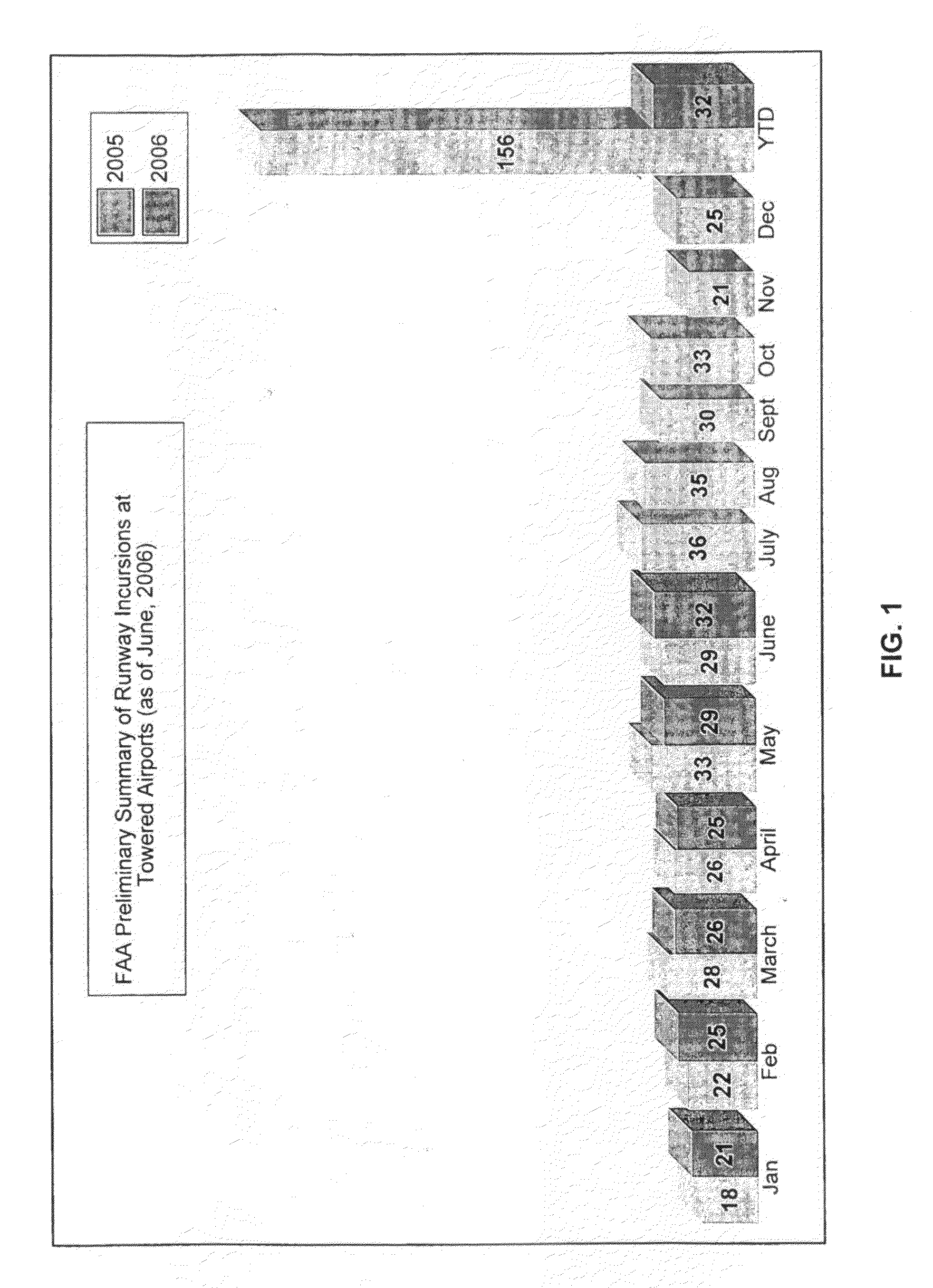
It is seen that there has been a significant increase in airport collisions during the twelve months preceding filing of this application.
Worldwide the ever-increasing volume of air traffic and the consequent constraints this makes on airport infrastructure has turned runway incursions into a global problem of epidemic proportions.
The FAA further declared that both incidents looked to be air-traffic controller errors.
Clearly these statistics are indicative of the failure of current systems to provide an airport anti-
collision system that responds in sufficient to allow corrective action to be taken in the increasingly dense environment of congested airports.

