Method of determining laser stabilities of optical material, crystals obtained with said method, and uses of said crystals

a technology of optical material and laser stability, which is applied in the field of determining laser stability of optical material, crystals obtained with said method, and use of said crystals, can solve the problems of increasing the sodium-stabilized f-centers by further irradiation and significant increase of measured induced fluorescence signals

Inactive Publication Date: 2010-05-06
HELLMA MATERIALS
View PDF7 Cites 21 Cited by
  • Summary
  • Abstract
  • Description
  • Claims
  • Application Information

AI Technical Summary

Benefits of technology

[0015]It is an object of the present invention to further improve the current method for evaluating laser-stable materials and to provide...

Problems solved by technology

This means that an increase of the sodium-stabilized F-centers by further irradiation could not be expected.
This shows th...

Method used


Image

  • Method of determining laser stabilities of optical material, crystals obtained with said method, and uses of said crystals
  • Method of determining laser stabilities of optical material, crystals obtained with said method, and uses of said crystals
  • Method of determining laser stabilities of optical material, crystals obtained with said method, and uses of said crystals

Examples


Embodiment Construction

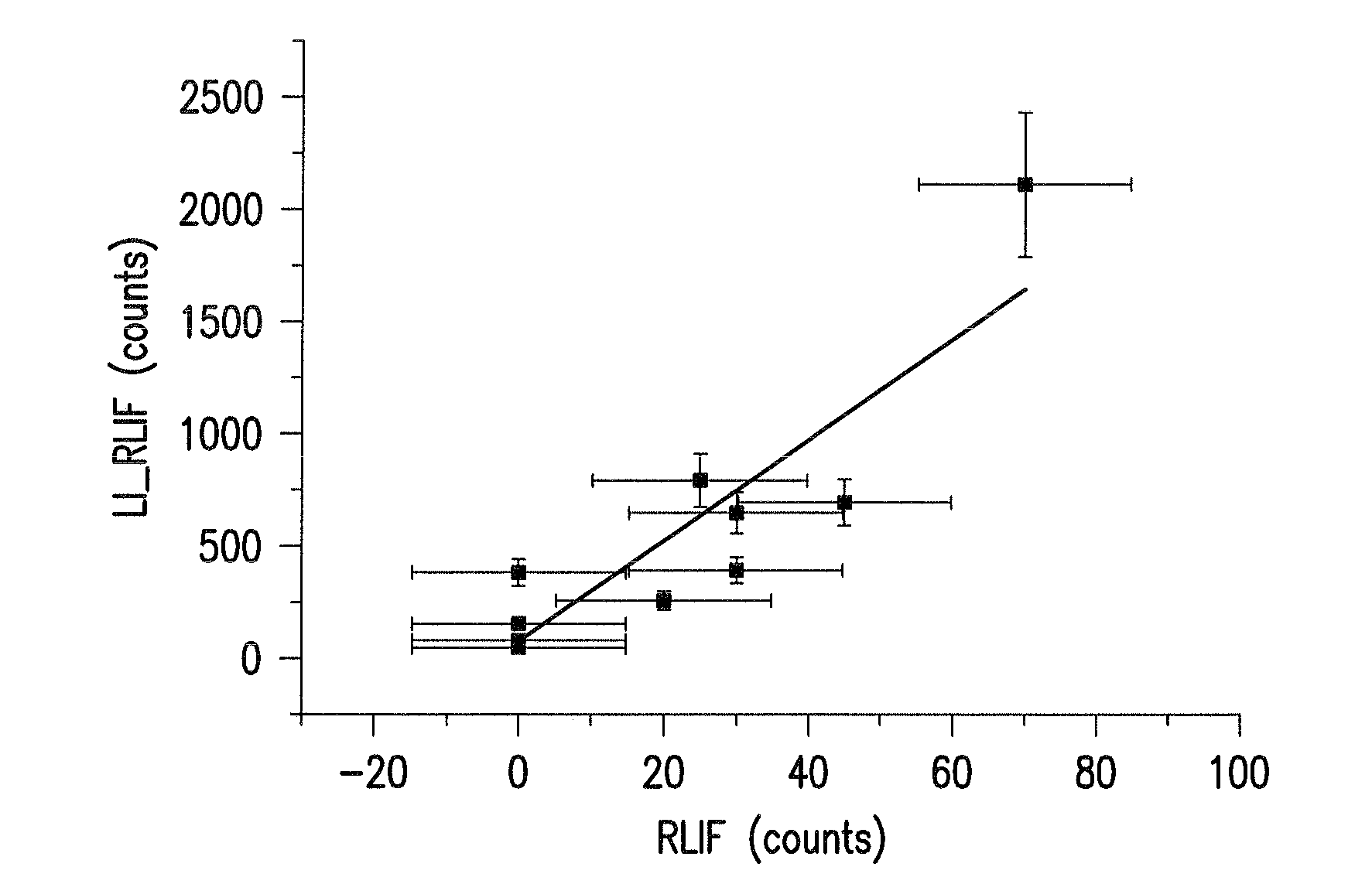
[0046]Different calcium fluoride crystals described by EP 1 890 131 A2 as laser-stable or laser radiation resistant were irradiated with 25 million pulses of 50 mJ / cm2 from a pulsed laser and subsequently the laser-induced fluorescence signals were measured with a CCD camera by the same measurement methods as previously in the first measurement of induced fluorescence. The results are shown in FIG. 1.

[0047]The light induced fluorescence signal prior to the energetic irradiation is plotted in FIG. 1 against the induced fluorescence signal after the extremely energetic irradiation. As can be ascertained from FIG. 1 the five samples according to the prior art method that had hardly any induced fluorescence had an induced fluorescence of between about 100 and 400 counts. One sample, which only had about 20 counts when exposed to a conventional irradiation, had an induced fluorescence of about 260 counts. This shows that the improved method for selecting optical material according to t...


PUM


Abstract

A method of selecting suitable laser-stable optical material for making an optical element, especially for transmission at wavelengths under 200 nm, is described. It includes a first pre-irradiation to produce radiation damage, subsequent excitation of induced fluorescence with light at between 350 to 700 nm at least ten minutes after the first pre-irradiation and measurement of induced fluorescence intensities at one or more wavelengths between 550 nm and 810 nm. After the fluorescence intensity measurement a second pre-irradiation is performed with an at least 1000-fold higher energy than in the first pre-irradiation and then induced fluorescence intensities are again measured to determine the increase in the fluorescence intensities. The materials determined to have suitable laser stability are used for making lenses, prisms, light-conducting rods, optical windows and optical devices for DUV lithography, especially steppers and excimer lasers, integrated circuits, computer chips as well as other electronic devices.

Description

CROSS-REFERENCE[0001]The invention claimed and described herein below is also described in German Patent Application DE 10 2008 054 148.6, filed Oct. 31, 2008 in Germany. The aforesaid German Patent Application provides the basis for a claim of priority for the instant invention under 35 U.S.C. 119 (a)-(d).BACKGROUND OF THE INVENTION[0002]1. Field of the Invention[0003]The present invention relates to a method of evaluating suitable optical material for making optical elements for high-energy radiation, especially with a wavelength under 200 nm, and to the optical material obtained with this method and their uses.[0004]2. Description of the Related Art[0005]It is known that materials from which optical elements are made absorb more or less of the light or radiation that passes through them, so that the intensity of the light and / or the radiation is generally less after passing through an optical element than before passing through it. It is also known that the extent of the absorpti...

Claims


Application Information

Patent Timeline
IPC IPC(8): C01F11/22G01T1/10
CPCG01N21/6402
Inventor NATURA, UTEPARTHIER, LUTZSALDERN, JOHANN-CHRISTOPH VON
Owner HELLMA MATERIALS
Why Eureka
Try Eureka