Filtration system

a technology of membrane systems and filtration membranes, applied in the direction of membranes, filtration separation, separation processes, etc., can solve the problems of media bed filtration, unsuitable and/or uneconomical to run in many applications, and inability to achieve the effect of reducing the concentration of ions

Active Publication Date: 2010-06-03
H2OIL&GAS
View PDF9 Cites 16 Cited by
  • Summary
  • Abstract
  • Description
  • Claims
  • Application Information

AI Technical Summary

Benefits of technology

[0078]wherein the filtration membrane is capable of removing particulates and/or suspended solids from reaching the reverse osmo

Problems solved by technology

Although many systems exist in the art for reducing total dissolved salts from water, many of these systems suffer from a number of disadvantages.
However, media beds typically have a large footprint and can be of significant weight.
Both of these factors mean that media bed filtration may be unsuitable and/or uneconomic to run in many applications, such as offshor

Method used


Image

  • Filtration system
  • Filtration system
  • Filtration system

Examples


example 1

[0136]FIG. 7 represents a comparison of a membrane vessel arrangement using eight element vessels according to the present invention with a prior art arrangement of six element membrane vessels located end to end.

[0137]As shown in FIG. 7, the membrane vessel arrangement according to the present invention has a significant reduction in footprint with a volume of 990 compared to the prior art arrangement of 1056. This is extremely important when working offshore where space on oil platforms is extremely limited.

[0138]FIG. 7 shows that prior art eight inch (203.2 mm) systems have a volume of 1056 and sixteen inch (406.4 mm) systems have a volume of 896. In contrast, using the arrangements of the present invention, a significant saving in volume may be found with the present invention eight inch (203.2 mm) system units having a volume of 990 and the sixteen inch (406.4 mm) system having a volume of 480. As will be understood, these are significant space saving reductions.

example 2

Improved Power Consumption

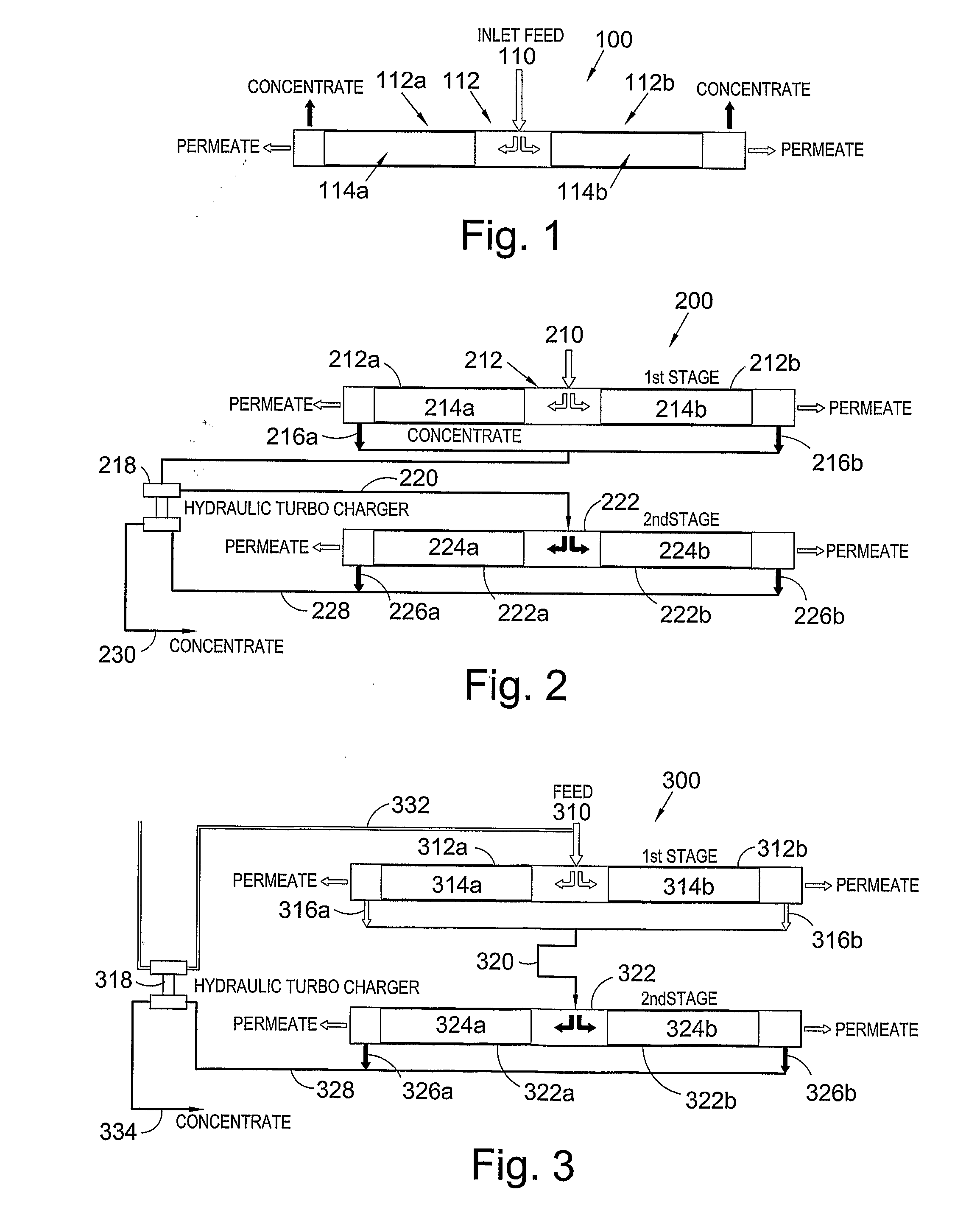
[0139]In this Example, we have used the membrane vessel arrangement 200 shown in FIG. 2.

[0140]Using Hydraulic Turbocharger (HTC) for the following conditions:

1st stage membrane pressure requirement: 28 barg (2.9 MPa)1st stage concentrate outlet pressure:25.5 barg (2.65 MPa)2nd stage inlet pressure requirement:31.5 barg (3.25 MPa)2nd stage concentrate outlet pressure: 23 barg (2.4 MPa)(without boost)System recovery:75%Pump Efficiency (Hydraulic):75%Pump Motor efficiency:90%HTC Efficiency:74.3%  HTC Pressure boost: 6.2 barg (0.72 MPa)

Based on 100 m3 / h system feed flow:

KWkW / m3Pump power without HTC147.81.48Pump power with HTC135.41.35Saving with HTC8.4%

There is therefore a power saving of 8.4% by using a hydraulic turbocharger.

example 3

Improved Power Consumption

[0141]Using the membrane vessel arrangement shown in FIG. 3, improved power consumption is found.

[0142]Using a Hydraulic Turbocharger (HTC) for the following conditions:

Inlet membrane pressure requirement:35 barg (3.6 MPa)Concentrate outlet pressure:31 barg (3.1 MPa)System recovery:75%Pump Efficiency (Hydraulic):75%Pump Motor efficiency:90%HTC Efficiency:74.3%  HTC Pressure boost: 4.6 barg (0.56 MPa)

Based on 100 m3 / h system feed flow:

KWkW / m3Pump power without HTC147.81.48Pump power with HTC128.31.32Saving with HTC11%

There is therefore a power saving of 11% using a hydraulic turbocharger.

Summary

[0143]Some improvements using the membrane vessel arrangements according to the present invention are summarised as follows:

System withCartridgeSystem withPresentfilter pre-Media filterInventiontreatment onlypretreatmentArea CalculationMedia Filters——157 m2Cartridge Filters— 44 m2 44 m2SRU Pumps108 m2108 m2108 m2CIP 22 m2 22 m2 22 m2Membrane Trains162 m2149 m2149 m2To...


PUM

PropertyMeasurementUnit
Timeaaaaaaaaaa
Energyaaaaaaaaaa
Permeation propertiesaaaaaaaaaa

Abstract

A filtration system includes a vessel for housing at least two filtration elements. One or more of the filtration elements is a reverse osmosis membrane or a nanofiltration membrane and one of the other filtration elements is a microfiltration or ultrafiltration membrane. The vessel has an inlet port for providing a liquid feed to the filtration elements, an outlet port for directing a permeate produced by the elements from the vessel and an outlet port for directing a concentrate produced by the elements from the vessel. A number of vessels can be provided in a parallel arrangement and/or a series arrangement and the vessels can be arranged so as to allow regeneration of the microfiltration or ultrationfiltration membranes from another vessel in the arrangement.

Description

CROSS-REFERENCE TO RELATED APPLICATION[0001]This application corresponds to International Application No. PCT / GB2008 / 000377, filed Feb. 4, 2008, which claims benefit of British Application No. 0702214.8, filed Feb. 6, 2007, all of which are incorporated herein in their entirety by reference thereto.FIELD OF THE INVENTION[0002]The present invention relates to filtration membrane systems. In particular, the present invention relates to nanofiltration and reverse osmosis membrane systems.BACKGROUND OF THE INVENTION[0003]Although many systems exist in the art for reducing total dissolved salts from water, many of these systems suffer from a number of disadvantages.[0004]For example, one existing method for water treatment involves transferring the water through a number of graded beds of filtration media. This acts as a pre-treatment for the water. However, media beds typically have a large footprint and can be of significant weight. Both of these factors mean that media bed filtration ...

Claims


Application Information

Patent Timeline
IPC IPC(8): B01D61/02B01D61/14B01D65/02
CPCB01D61/022B01D2321/02B01D61/027B01D61/08B01D61/142B01D61/145B01D61/147B01D61/18B01D61/58B01D65/02B01D2317/02B01D2317/022B01D2317/04B01D2319/025B01D2321/04C02F1/44C02F1/441C02F1/442C02F1/444B01D61/025B01D61/026B01D61/146B01D61/029B01D61/149
Inventor THERON, DOUGLAS ARNOLDUSMCMONAGLE, ANTHONY JOHNMCNULTY, MARK ALBERTBARRIE, SCOTT ALEXANDER
Owner H2OIL&GAS
Why Eureka
Try Eureka