
Chiral Metamaterials

a metamaterial and chiral technology, applied in the field of chiral metamaterials, can solve the problems of stereochemically distinct 3-d structures, and achieve the effects of enhancing biomedical imaging, efficient control of dng transmission bands, and low cos

Inactive Publication Date: 2010-06-10
UNIVERSITY OF MASSACHUSETTS LOWELL
View PDF5 Cites 131 Cited by
  • Summary
  • Abstract
  • Description
  • Claims
  • Application Information

AI Technical Summary

Benefits of technology

The present invention relates to a metamaterial that includes an array of discrete resonators with specific shapes that can be designed to have simultaneously negative effective electric permittivity and negative effective magnetic permeability in a given frequency region. The metamaterial can be used in various applications such as sensors, imaging devices, and communication devices. The invention also includes a method for designing the metamaterial and a method for splitting incident electromagnetic radiation. The technical effects of the invention include improved performance and functionality of metamaterials in the negative permittivity and negative permeability regions, as well as increased design flexibility and improved sensitivity to electromagnetic radiation.

Problems solved by technology

For example, drugs are usually sufficiently complex to typically contain one or more chiral centers that result in the existence of stereochemically distinct 3-D structures.

Method used


Image

  • Chiral Metamaterials
  • Chiral Metamaterials
  • Chiral Metamaterials

Examples


example 1

Simulation and Modeling of Metamaterials having “y-type” Shaped Resonators

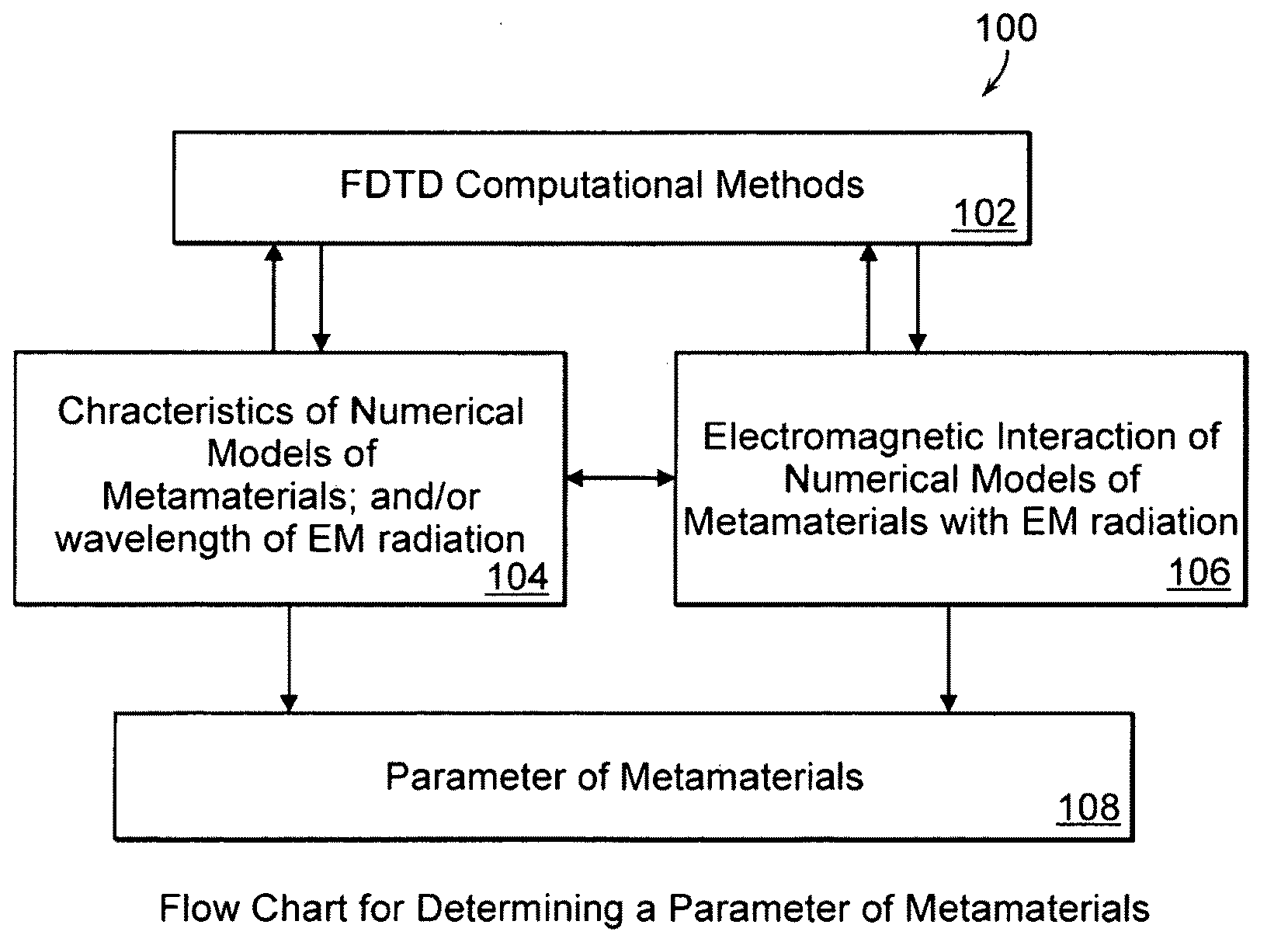
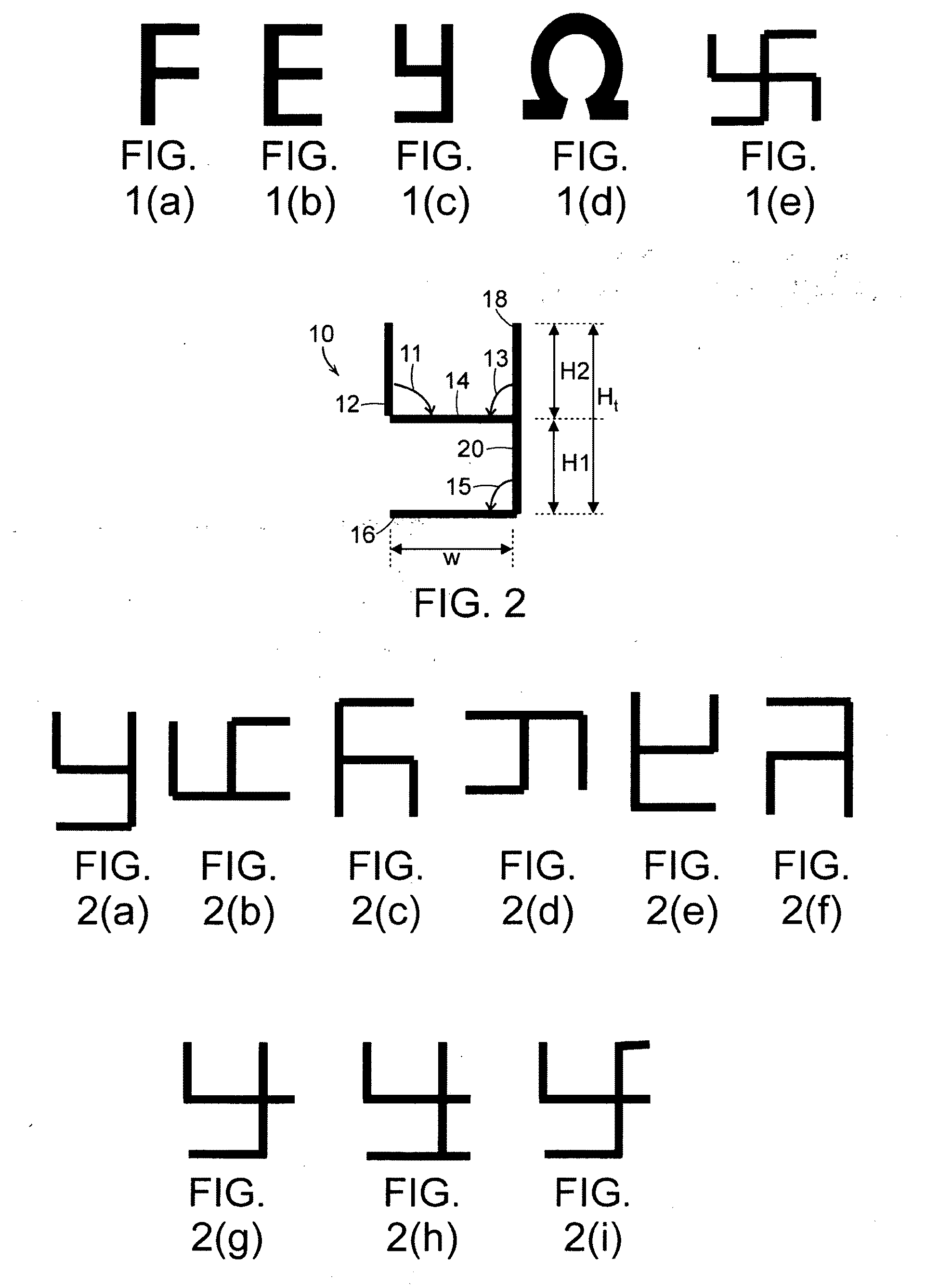
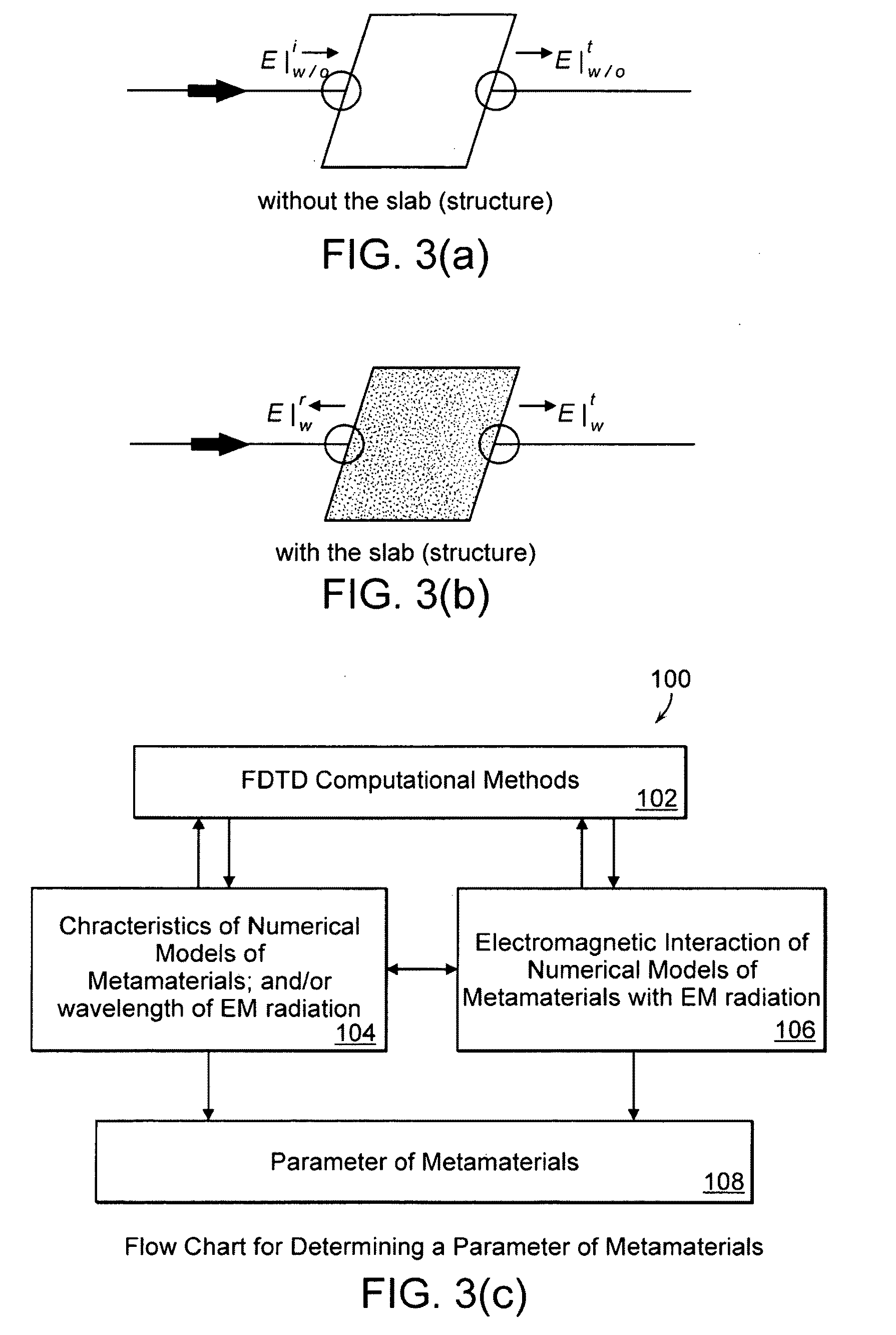
[0118]Three-dimensional (3D) Finite-Difference Time-Domain (FDTD) analysis of the electromagnetic wave interaction of an array of “y-type shaped” resonator was conducted to obtain transmission and reflection coefficients in the terahertz (THz) frequency regime. Referring to FIGS. 4(a)-4(b), FDTD model 30 was composed of a semi-infinite periodic array of “y-type shaped” resonators 10 embedded within free space 32 inside a waveguide. Perfect electric conductor (PEC) walls and perfect magnetic conductor (PMC) walls located in the transverse direction and in the direction of periodicity, respectively, formed the boundary conditions of FDTD model 30. Gaussian beam 34, normally propagating through the waveguide was used as a source of the excitation at one of the two input ports. Uniaxial perfectly matched layers (UPML) 36 and 38 were set at the ends of the ports to absorb the outgoing waves.

[0119]Maxwell's three di...

example 2

Designing Double Negative Metamaterials: Prediction of Electric Resonant Frequency and Magnetic Resonant Frequency of “F-type”, “E-type” and “y-type” Shaped Resonators

[0125]The Drude-Lorentz model of the effective permittivity for a resonator including an array of rods is given as described above in Equation (7). As shown in FIG. 6(b), the two horizontal lines introduced in each break of the rod shape of FIG. 6(a) can enlarge the surface area of the capacitance, Ce. This will lower the electric resonant frequency ωe0. Similarly, by bending the vertical rod of FIG. 6(a) and creating the “S” shape as shown in FIG. 6(c), ωe0 and ωep can be further lowered. F-type, E-type, and y-type shaped resonators are all constructed with main vertical axes (vertical components) combined with arms (horizontal components) that can increase the value of Ce (see FIG. 6(d)). Thus, it is expected that these shapes will scale down the location of the negative permittivity (−ε), based upon the observations...

example 3

Transmittance Properties of Metamaterial Models

[0129]Three-dimensional Finite-Difference Time-Domain (FDTD) analysis of the electromagnetic wave interactions with metamaterials models was conducted to obtain the transmission / reflection coefficients for chiral metamaterials with resonators in the nanoscale dimension range (visible, ultraviolet, near-IR regions). An FDTD model was composed of an infinite periodic array of S-type, F-type, E-type or y-type shaped resonators embedded within a dielectric slab located inside a waveguide. Perfect electric conductor (PEC) walls and perfect magnetic conductor (PMC) walls located in the transverse direction and in the direction of periodicity respectively, form the boundary conditions of the model. A Gaussian beam, normally propagating through a slab was used as the source of excitation, at one of the two input ports.

[0130]The results shown in FIG. 8(a) were obtained from the computation of the S-type, F-type, E-type and y-type shaped resonato...


PUM

PropertyMeasurementUnit
near-IR wavelengthsaaaaaaaaaa
anglesaaaaaaaaaa
wavelengthaaaaaaaaaa

Abstract

A metamaterial includes a dielectric substrate and an array of discrete resonators at the dielectric substrate, wherein each of the discrete resonators has a shape that is independently selected from: an F-type shape; an E-type shape; or a y-type shape. A parameter of a chiral metamaterial is determined and a chiral metamaterial having such a parameter is prepared by the use of a model of the chiral metamaterial. The metamaterial model includes an array of discrete resonators. In one embodiment, each of the discrete resonators has a shape that is independently selected from the group consisting of: an F-type shape; an E-type shape; and a y-type shape. To the metamaterial model, electromagnetic (EM) radiation, preferably plane-polarized EM radiation in a visible, ultraviolet or near-infrared region, having at least one wavelength that is larger than the largest dimension of at least resonator of the metamaterial model, is applied. Varying at least one characteristic of the metamaterial model and / or at least one wavelength of the applied EM radiation modulates EM interaction of the applied EM radiation with the metamaterial model, thereby determining a parameter of the chiral metamaterial. By the use of a model of the chiral metamaterial, a number of discrete resonators of a chiral metamaterial that are arrayed in a direction perpendicular to a propagation axis of EM radiation is also determined.

Description

RELATED APPLICATION[0001]This application is a continuation-in-part application of U.S. application Ser. No. 11 / 334,954, filed Jan. 18, 2006, which claims the benefit of U.S. Provisional Application No. 60 / 644,742, filed Jan. 18, 2005. The entire teachings of the above-mentioned applications are incorporated herein by reference.BACKGROUND OF THE INVENTION[0002]“Chiral metamaterials” are chiral (i.e., right- or left-handed) artificial materials that include repeating array(s) of small conducting structures (“resonators”) and exhibit a unique macroscopic property due to fine scale repetition of the small conducting structures (e.g., sizes smaller than a wavelength of applied radiation). In particular, chiral metamaterials possessing both negative effective electric permittivity and negative effective magnetic permeability within substantially the same frequency region are believed to behave in very unusual ways when interacting with electromagnetic (EM) radiation, for example: a) bend...

Claims


Application Information

Patent Timeline
Patent Type & Authority Applications(United States)
IPC IPC(8): H01P7/10H01F7/06H05K3/30
CPCH01P1/20Y10T29/4913Y10T29/4902
Inventor AKYURTLU, ALKIMMARX, KENNETH A.WONGKASEM, NANTAKAN
Owner UNIVERSITY OF MASSACHUSETTS LOWELL
Learn More