Wire Grid and Manufacturing Method Thereof

Active Publication Date: 2010-06-10
MURATA MFG CO LTD
View PDF11 Cites 7 Cited by
  • Summary
  • Abstract
  • Description
  • Claims
  • Application Information

AI Technical Summary

Benefits of technology

[0011]Thus, an object of the present invention is to solve the problem with the use of the wires described above and the problem with the use of the substrate or base material, a

Problems solved by technology

In the case of a wire grid with a diameter of 100 mm, metal wires have a length of about 100 mm, and it is thus difficult to tighten the long thin metal wires parallel to each other.
More specifically, the tension easily cuts the metal wires, or causes an interval between the metal wires to get irregular, thus leading to difficulty in m

Method used


Image

  • Wire Grid and Manufacturing Method Thereof
  • Wire Grid and Manufacturing Method Thereof
  • Wire Grid and Manufacturing Method Thereof

Examples


first embodiment

[0041]A metal plate for a wire grid and a method for manufacturing the wire grid according to a first embodiment will be described with reference to FIGS. 2 to 4.

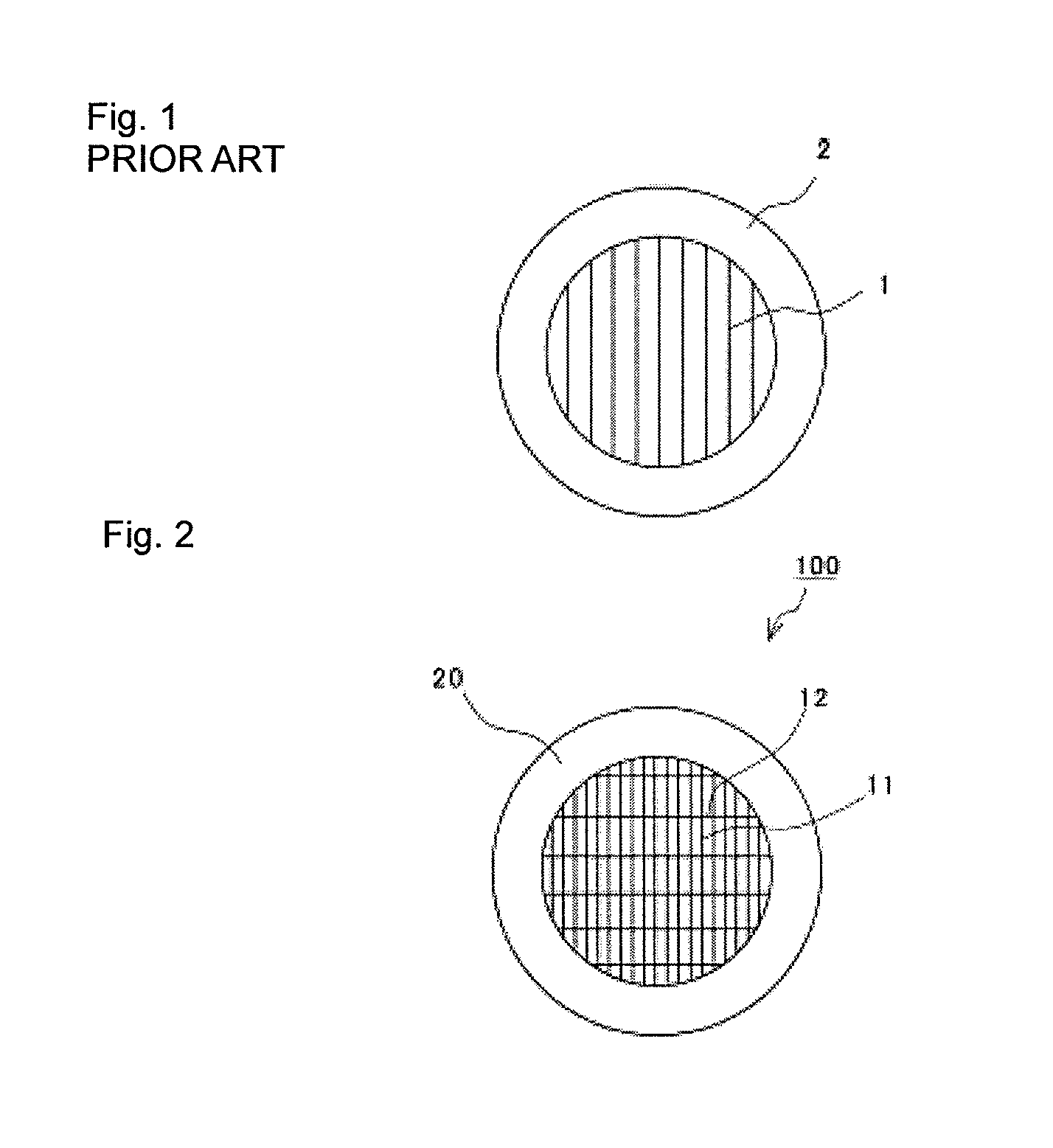
[0042]FIG. 2 is a plan view of a wire grid 100 according to the first embodiment. This wire grid 100 is obtained by attaching a textile to a ring frame body 20, the textile including a plurality of stainless steel wires (hereinafter, simply referred to as stainless wires) 11 extending vertically and silk yarns 12 extending horizontally while crossing one by one alternately with respect to the stainless wires 11.

[0043]When the wire grid 100 shown in FIG. 2 is used as a polarizer or analyzer, electromagnetic waves are made incident in a direction perpendicular to a surface of the wire grid 100. With incident electromagnetic waves having a plane of polarization parallel to the stainless wires 11 of the wire grid 100, the electric field component of the electromagnetic waves generates an electric current in the stainless wires ...

second embodiment

[0062]A metal plate for a wire grid and a method for manufacturing the wire grid according to a second embodiment will be described with reference to FIG. 5.

[0063]While the wire grid fabric with the insulating yarns left in place is used in the first embodiment, this second embodiment provides a wire grid fabric fixed in a frame body with insulating yarns removed.

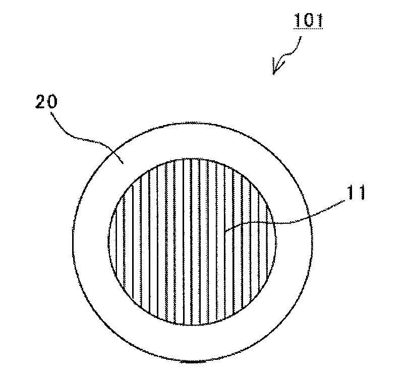
[0064]FIG. 5 is a plan view of a wire grid 101 according to the second embodiment. This wire grid 101 is obtained by attaching a textile to a ring frame body 20 and then removes the silk yarns, the textile including a plurality of stainless wires 11 extending vertically and silk yarns 12 extending horizontally while crossing one by one alternately with respect to the stainless wires 11.

[0065]Specifically, processing such as burning the insulating yarns causes the yarns to substantially disappear. Alternatively, chemically soluble yarns are used as the insulating yarns, and the insulating yarns are dissolved in a liquid, wit...

third embodiment

[0067]While the textile with the conductive yarns and the insulating yarns is used in the first and second embodiments, the third embodiment uses conductive yarns for both warp yarn and weft yarn.

[0068]FIG. 6 is a plan view of a wire grid 102 according to the third embodiment. This wire grid 102 is obtained by attaching a textile to a ring frame body 20, the textile including a plurality of stainless wires 11 extending vertically and stainless wires 13 extending horizontally while crossing one by one alternately with respect to the stainless wires 11.

[0069]The pitch for the stainless wires 11 as warp yarn is made to have the ¼ wavelength of a wavelength to be polarized and analyzed, whereas the pitch for the stainless wires 13 as weft yarn is made 10 times as long as a wavelength to be polarized. When the pitch for the stainless wires 13 as weft yarn is 5 or more times as long as the wavelength, the increase in loss due to the existence of the stainless wires 13 can be suppressed to...


PUM

PropertyMeasurementUnit
Lengthaaaaaaaaaa
Lengthaaaaaaaaaa
Diameteraaaaaaaaaa

Abstract

A textile made by weaving while crossing stainless wires as warp yarn and silk yarns as weft yarn one by one alternately, and this textile is attached to a frame body to configure a wire grid. The pitch for the stainless wires is determined depending on a wavelength to be polarized and analyzed. Furthermore, the silk yarns are removed if necessary. This configuration avoids problems with cutting of metal wire or irregular intervals between metal wires because of long fine metal wires tightened parallel to each other in the frame body, and problems such as multiple reflection or interference on a substrate or a base material because of fine wire patterns made by etching or the like with the use of the substrate or base material, thereby obtaining an easily-manufactured, low-cost and high-precision wire grid for polarization and analysis of electromagnetic waves.

Description

CROSS REFERENCE TO RELATED APPLICATIONS[0001]The present application is a continuation of International Application No. PCT / JP2008 / 062821, filed Jul. 16, 2008, and claims priority to Japanese Patent Application No. JP2007-217567, filed Aug. 23, 2007, the entire contents of each of these applications being incorporated herein by reference in their entirety.TECHNICAL FIELD[0002]The present invention relates to a wire grid which is, for example, a terahertz band or millimeter-wave band polarization component, and a method for manufacturing the wire grid.BACKGROUND ART[0003]Wire grids are polarization components commonly used in the field of optics or electromagnetic waves, and disclosed in, for example, Non-Patent Document 1. Furthermore, Patent Document 1 discloses the use of a wire grid for a terahertz band ellipsometer.[0004]FIG. 1 is a diagram illustrating the structure of a wire grid. The terahertz band wire grid has, as shown in FIG. 1, thin and long single metal wires 1 arranged...

Claims


Application Information

Patent Timeline
IPC IPC(8): G02B5/30D03D15/00
CPCG02B5/3058
Inventor FUJII, TAKASHIZAIKI, SHOJI
Owner MURATA MFG CO LTD
Why Eureka
Try Eureka