Humidity sensor and method of manufacturing the same

a technology of humidity sensor and sensitive layer, which is applied in the field of humidity sensor, can solve the problems of low sensitivity of humidity sensor using sensitive layer, high hysteresis in response to its surroundings, and response time of several minutes, and achieves low hysteresis, high sensitivity, and quick response time

Active Publication Date: 2010-06-17
ELECTRONICS & TELECOMM RES INST
View PDF10 Cites 46 Cited by
  • Summary
  • Abstract
  • Description
  • Claims
  • Application Information

AI Technical Summary

Benefits of technology

[0026]The present invention is directed to a humidity sensor having high sensit...

Problems solved by technology

However, the conventional humidity sensor using the sensitive layer has low sensitivity since it uses a planar electrode, and responds with high hysteresis in response to its surroundings.
In addition, since the sensitive layer is difficult to reset to an initial state, its response time is several minutes.
In the conventional humidity sensor, a large drift in performance is shown due to condensation of moisture on a sensor electrode or a sensitive layer, and durability is decreased due to high stress generated in the sensor structure when humidity is high.
Accordingly, when the micro humidity sensor device is manufactured by a semiconductor process, it requires high production costs and a long manufacture period, leading to a decreasing yield.
However, these methods have a problem in developing a unique forming process for a humidity sensitive layer material to be used.
However, it cannot control the depth and shape of the cavity 102, both sides of the substrate must be processed, and production costs are raised as the device's die becomes larger.
Moreover, according to this method, a support layer is formed only of the insulating layer 104 in a suspended structure, so that it is vulnerable to repetitive thermal shock and also weak in structure.
Since the heater is formed by special patterning such as printing, and one substrate is mounted on the other substrate, so that they canno...

Method used


Image

  • Humidity sensor and method of manufacturing the same
  • Humidity sensor and method of manufacturing the same
  • Humidity sensor and method of manufacturing the same

Examples


Embodiment Construction

[0038]Hereinafter, the present invention will be described with reference to the accompanying drawings in detail. This invention may, however, be embodied in different forms and should not be construed as limited to the embodiments set forth herein. Rather, these embodiments are provided so that this disclosure will be thorough and complete, and will fully convey the scope of the invention to those skilled in the art. Like numbers refer to like elements throughout the specification.

[0039]Throughout the specification, one part “includes” a component, which, not illustrated otherwise, does not mean another component is omitted, but another component may be further included.

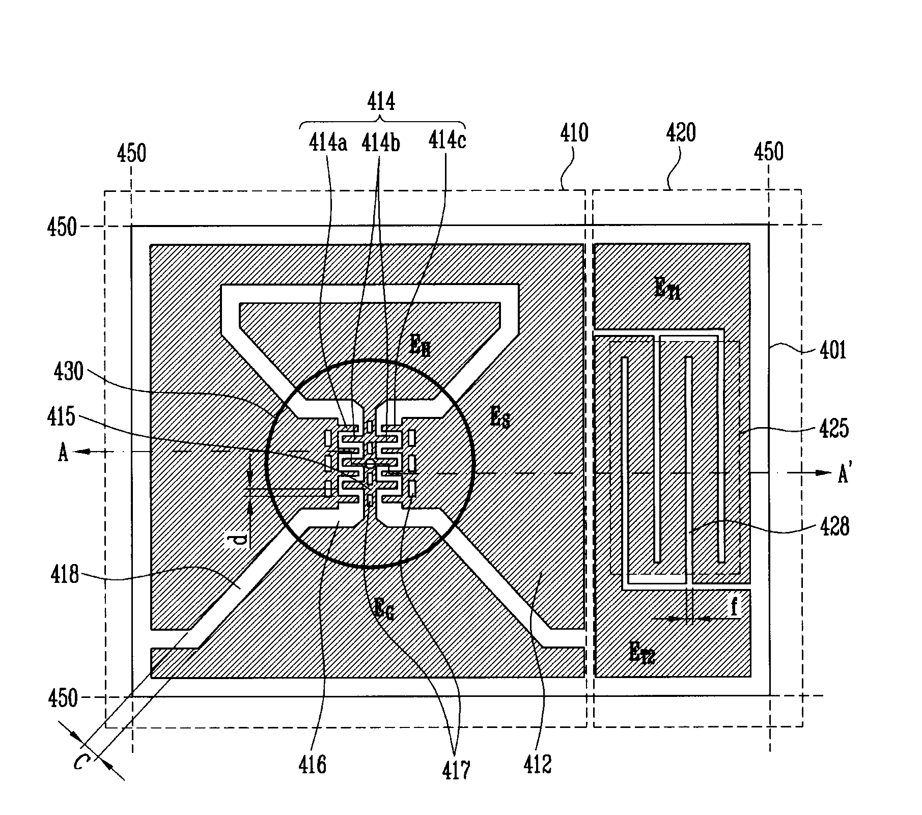
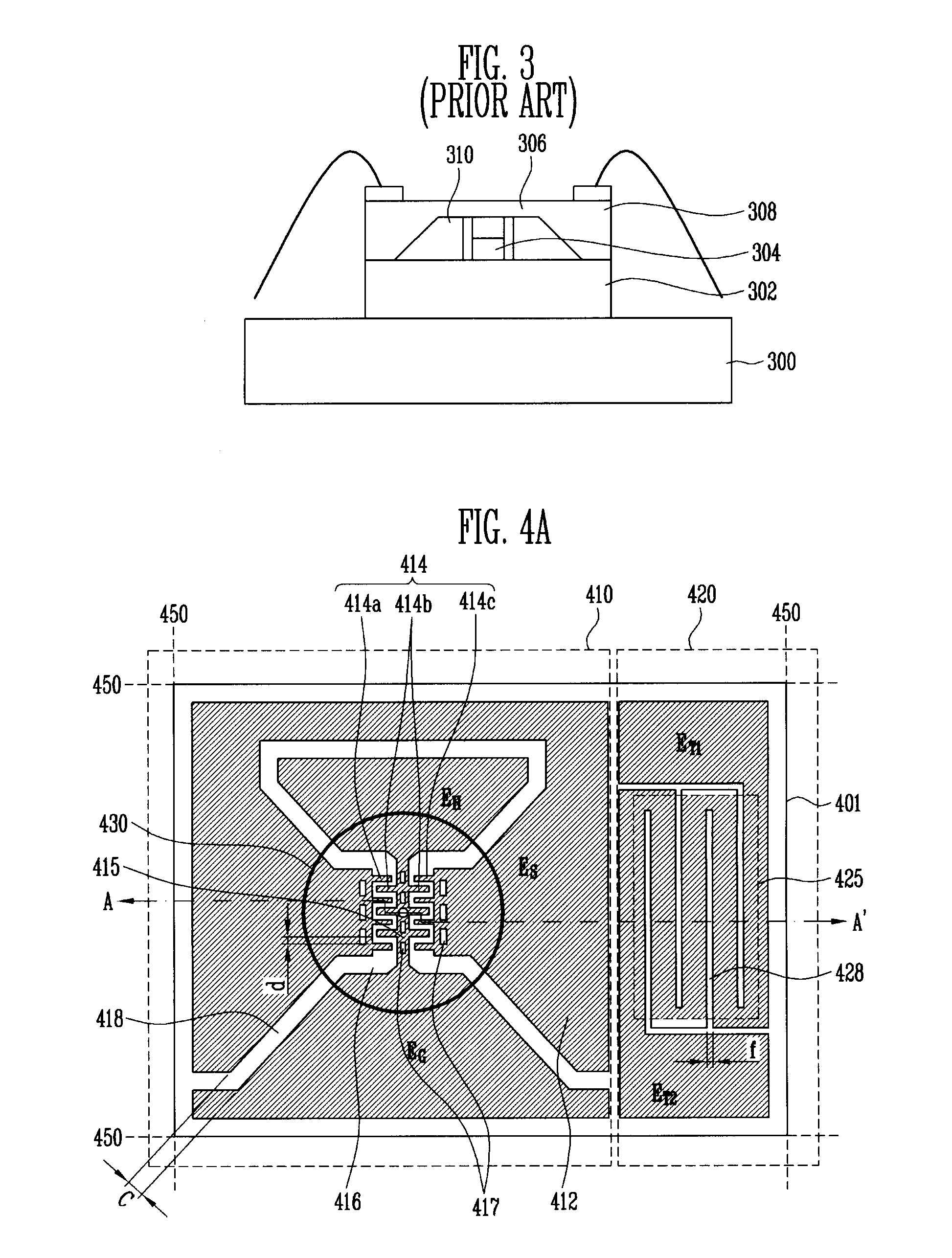
[0040]FIG. 4A is a plan view of a humidity sensor according to an exemplary embodiment of the present invention, and FIG. 4B is a cross-sectional view taken along line A-A′ of FIG. 4A.

[0041]Referring to FIGS. 4A and 4B, the humidity sensor according to an exemplary embodiment of the present invention includes a subs...


PUM


Abstract

Provided are a humidity sensor and a method of manufacturing the same. The humidity sensor has high sensitivity, quick response time, improved temperature characteristics, low hysteresis and excellent durability. Moreover, for the humidity sensor, a humidity sensitive layer may be formed of various materials. The humidity sensor may be manufactured in a small size on a large scale.
The humidity sensor includes a substrate, an open cavity with an open upper portion formed to have a depth and a width in the substrate, a plurality of electrode pads formed on the substrate, a heater connected to one pad of the electrode pads at one end, and connected to another pad of the electrode pads at the other end to be suspended over the open cavity, a plurality of sensing electrodes formed on the same plane as the heater, and suspended over the open cavity to output a sensed signal to the electrode pads, a humidity sensitive layer formed on the heater and the sensing electrodes, suspended over the open cavity, and changed in characteristic according to the humidity, and an ambient temperature measurement part configured to measure the temperature around the humidity sensor, wherein the temperature is used as a reference temperature to control a heating temperature of the heater.

Description

CROSS-REFERENCE TO RELATED APPLICATION[0001]This application claims priority to and the benefit of Korean Patent Application No. 10-2008-0128848, filed Dec. 17, 2008, the disclosure of which is incorporated herein by reference in its entirety.BACKGROUND[0002]1. Field of the Invention[0003]The present invention relates to a humidity sensor and a method of manufacturing the same, and more particularly, to a humidity sensor which has high sensitivity and quick response properties, consumes less power to heat, has fast heating and cooling properties and high durability and is manufactured in an ultra small size, and a method of manufacturing the humidity sensor. The humidity sensor may use various kinds of materials to form a humidity sensitive layer, and may be mass-produced at low production costs in a simple process.[0004]2. Discussion of Related Art[0005]Recently, with growing interest in a ubiquitous environment for obtaining information about things centered around humans, there i...

Claims


Application Information

Patent Timeline
IPC IPC(8): G01N19/10B05D5/12B44C1/22
CPCG01N27/121G01N27/00G01N33/18G01N27/06B82Y15/00
Inventor JUN, CHI HOONKO, SANG CHOONCHOI, CHANG AUCKYU, BYOUNG GON
Owner ELECTRONICS & TELECOMM RES INST
Why Eureka
Try Eureka