Rotating-Plate Radial Turbine in Gas-Turbine-Cycle Configurations

a technology of rotating plates and radial turbines, which is applied in the direction of wind turbines with parallel air flow, liquid fuel engines, motors, etc., can solve the problems of unenviable transportation sector energy efficiency situation, complex design/construction of internal combustion reciprocating engines, and 45% of the maximum steam turbine cycle thermal efficiency, so as to reduce greenhouse gas emissions and improve cycle thermal efficiency. , the effect of improving the thermal efficiency

Inactive Publication Date: 2010-06-17
STANKOVIC BRANKO
View PDF0 Cites 1 Cited by
  • Summary
  • Abstract
  • Description
  • Claims
  • Application Information

AI Technical Summary

Benefits of technology

[0015]Provided it proves to be technically / technologically valid and feasible, this very efficient (in some special instances close to 100%) and conditionally zero-fuel-input power-generation concept would result in potentially huge cycle thermal efficiency improvements and hence likely in dramatic consequences in the future of energy supply & energy prices at the planet Earth. In addition, it could also become a very efficient means for reducing of greenhouse gases emissions and indirect establishing of their normal natural quantities in the Earth's atmosphere.

Problems solved by technology

However, with steam-boiler losses, the overall maximum steam-turbine cycle thermal efficiency is ˜45%.
Energy efficiency situation is particularly unenviable in the transportation sector, where gas turbines are typically used for propelling of aircrafts and internal-combustion reciprocating engines are typically used for propelling of motor vehicles.
In addition, internal-combustion reciprocating engines are much more complex in their design / construction.
Although modern power-producing systems achieve ever-increasing cycle thermal efficiencies, it appears that these improvements are not sufficient to enable converting bulk of Earth's fossil-fuels reserves into mechanical / electrical energy in an efficient, enough technically simple and enough cheap manner.
With current trend, future of our planet seems to be doomed, unfortunately.

Method used


Image

  • Rotating-Plate Radial Turbine in Gas-Turbine-Cycle Configurations
  • Rotating-Plate Radial Turbine in Gas-Turbine-Cycle Configurations
  • Rotating-Plate Radial Turbine in Gas-Turbine-Cycle Configurations

Examples


Embodiment Construction

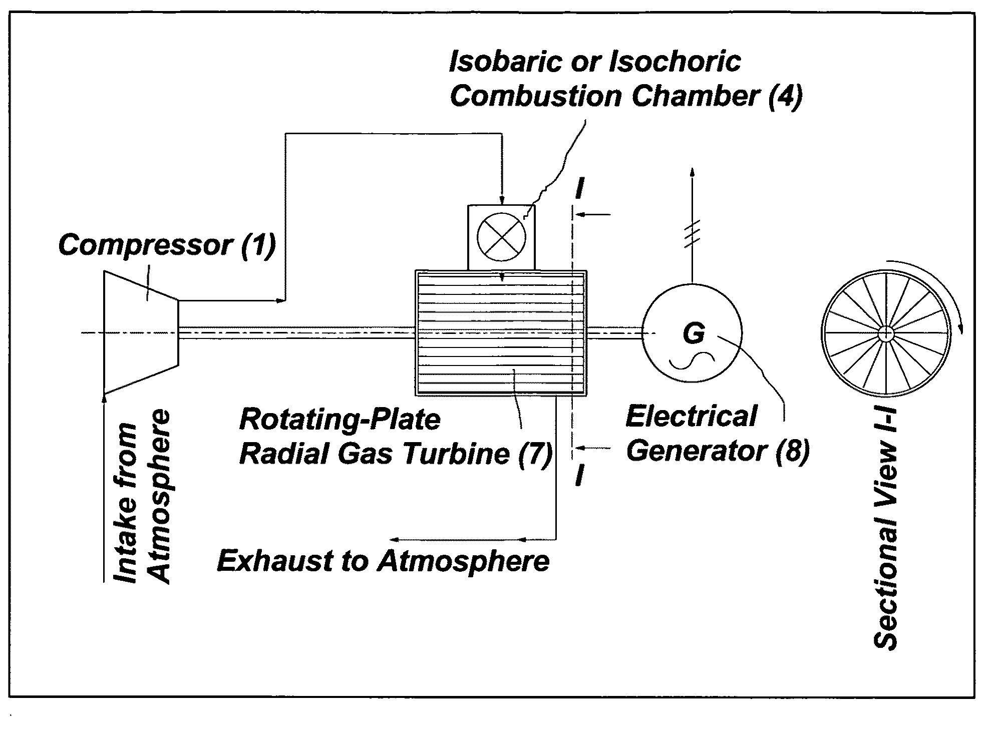
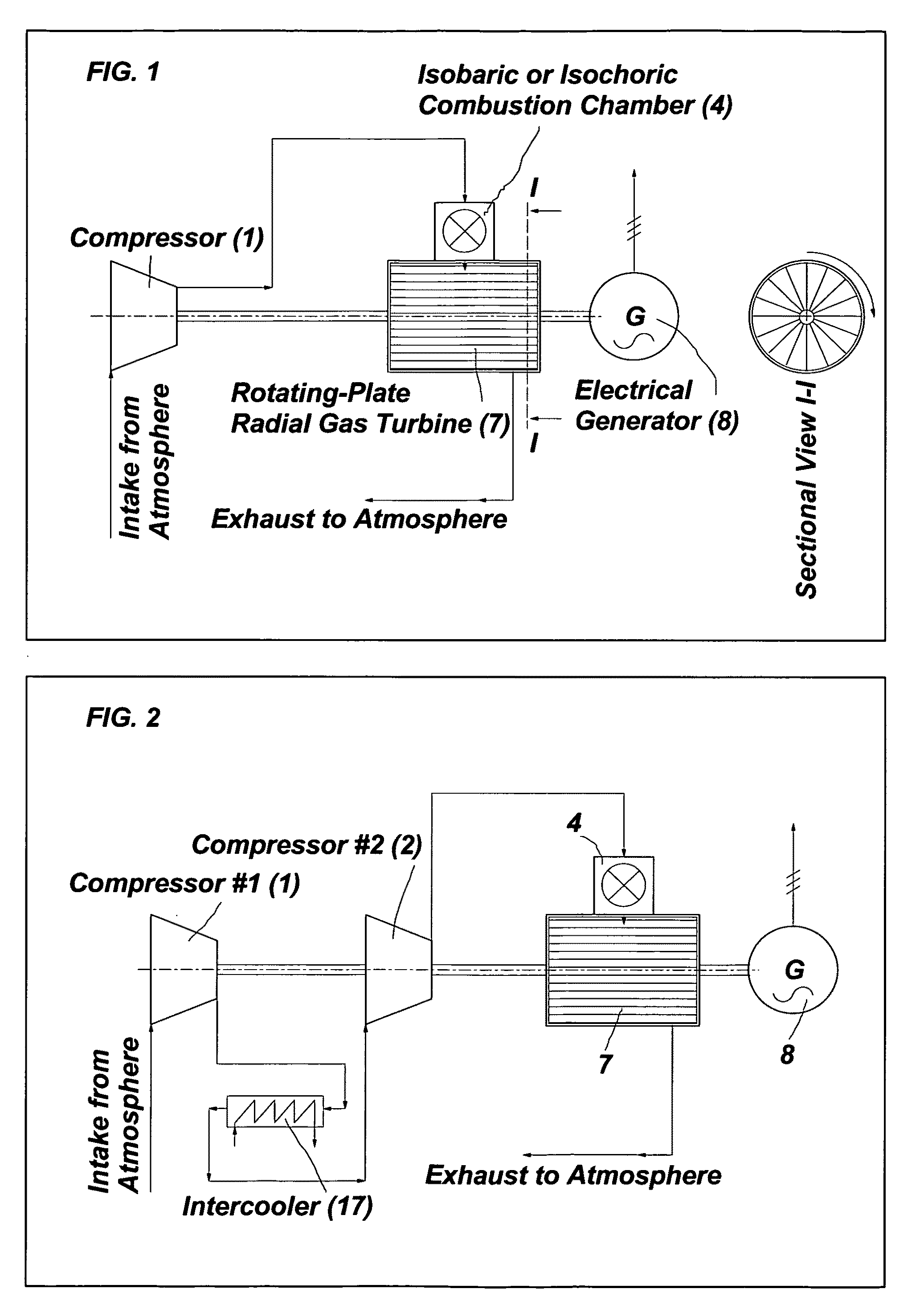
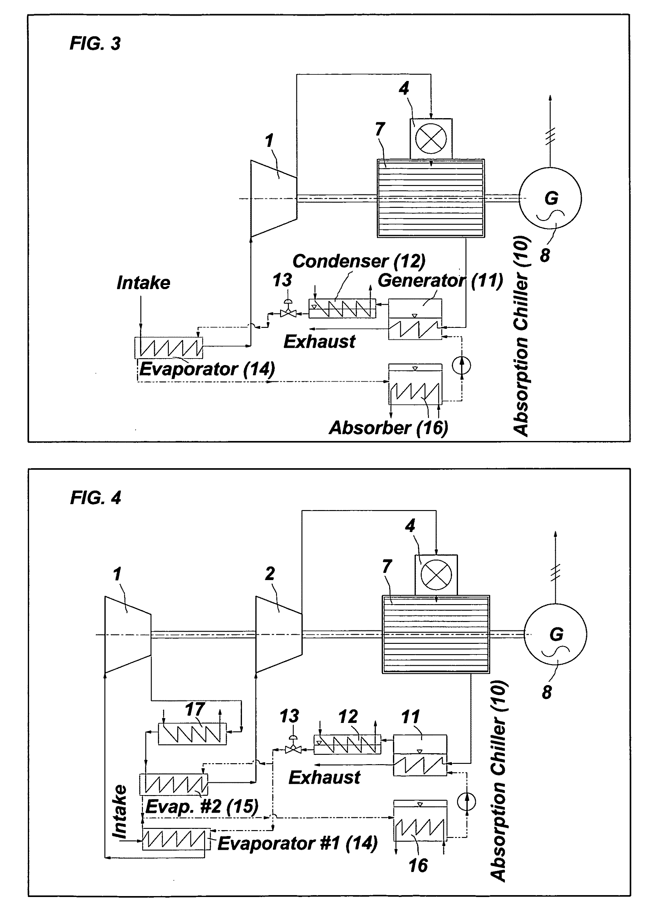
[0038]In this chapter a detailed description of preferred rotating-plate radial gas-urbine cycle configurations and explanation of corresponding thermodynamic diagrams will be given, with a more detailed explanation of the rotating-plate radial gas-turbine working principle.

[0039]This invention advocates the use of an innovation in the gas-turbine power-plants—a rotating-plate radial gas turbine, which is expected to be a significant improvement and to dramatically increase the GT power-plant cycle thermal efficiency. As already mentioned previously, the rotating-plate radial gas turbine is planned in the form of a rotating barrel with robust rectangular plates (“rotating plates”), performing the function and the role of turbine blades, fitted into a radial-turbine rotor, contained within a motionless rigid horizontal cylinder (casing). Physically it very much resembles an ordinary water mill with its simple and robust design and is similar to an impulse water turbine (“Pelton turbi...


PUM


Abstract

A novel power-producing concept is disclosed, employing a rotating-plate radial gas turbine in various gas-turbine cycle configurations. The “rotating-plate radial gas turbine” is a rotating barrel with robust rectangular plates fitted into the turbine rotor, performing the function and the role of turbine blades, contained within a motionless rigid horizontal cylinder (casing). Combustion can take place in the spaces confined between adjacent rotating plates and the static cylinder, thus enabling a practical achievement of the Atkinson cycle (constant-volume heat addition) with improved cycle thermal efficiency. Alternatively, two or more compressor stages can be combined to feed a single rotating-plate radial gas turbine in cascades, thus gradually increasing pressure of working gas within a volume bordered by adjacent un-cooled rotating plates of the radial gas turbine and the casing. Alternatively, a single compressor may be combined with one or more stages of an axial turbine for cascade feeding of a single rotating-plate radial gas turbine. This “isochoric stuffing” effect enables achievement of significantly and even drastically improved gas-turbine-cycle thermal efficiencies. Cycle heat addition may be either isobaric or isochoric in either an open-cycle or a closed-cycle configuration. Using a sufficiently efficient radial gas turbine, it is theoretically possible to obtain 100% cycle thermal efficiency in a simple radial-gas-turbine configuration with appropriately chosen compressor-stages compression pressure ratios.

Description

BACKGROUND OF THE INVENTION[0001]The concept disclosed in this invention relates to a means or a device (gas-turbine power plant) and method for generating of power from heat by employing an improved component—rotating-plate radial gas turbine. The concept has a potential to enable achievement of significantly and even drastically improved gas-turbine-cycle thermal efficiencies.[0002]In today's conditions of an ongoing and growing energy crisis and recently increased and accelerating global climate changes and global warming phenomena, world's governments, large companies and engineers / scientists are intensely interested in developing more energy-efficient and improved power-producing systems. Increased concentration of CO2-gas in the atmosphere is today recognized as the main culprit of global warming phenomena. Together with water vapor (H2O), CO2 represents the main and an unavoidable ingredient of flue gases resulting from combustion of fossil fuels (coal, fuel oil / petroleum, na...

Claims


Application Information

Patent Timeline
Patent Type & Authority Applications(United States)
IPC IPC(8): F01D5/14
CPCF01D5/04F05D2240/241F02C3/36F02C3/14
Inventor STANKOVIC, BRANKO
Owner STANKOVIC BRANKO
Why Eureka
Try Eureka