Cold gas dynamic spray apparatus, system and method

a spray apparatus and cold gas technology, applied in the direction of lighting and heating apparatus, coatings, combustion types, etc., can solve the problems of clogging of the nozzle, high equipment and operational cost, and high cost of upstream powder feeding technique, etc., to achieve the effect of limiting spray efficiency, easy clogging, and optimal operation rang

Active Publication Date: 2010-06-17
NAT RES COUNCIL OF CANADA
View PDF27 Cites 36 Cited by
  • Summary
  • Abstract
  • Description
  • Claims
  • Application Information

AI Technical Summary

Benefits of technology

[0038]Two or more particle inlets at a location between the throat and the second end permit particulate material to enter the flow path of the nozzle at a location. In a de Laval type nozzle, the location is at the diverging portion of the nozzle. The flow path is substantially linear and describes the main gas flow direction through the nozzle. The two or more particle inlets have inner diameters at the junction with the inner wall of the nozzle that are smaller than the inner diameter of a particle inlet used in a system having only one particle inlet. There exists an optimal operational range for the ratio between the total cross-sectional area of particle inlets and the cross-sectional area of the nozzle at the location of the particle inlets on the nozzle. Particle inlets with cross-sectional areas that are too small are easily clogged during the cold spray process, especially during starting and stopping of particle feeding. In addition, particle inlets that are too small can limit spray efficiency (limiting the maximum system capability for particle delivery). On the other hand, particle inlets having cross-sectional areas that are too large can cause turbulent flow in the nozzle, significantly reducing particle velocity and deposition efficiency.
[0039]Thus, the ratio between total cross-sectional area of particle inlets and the cross-sectional area of the nozzle is preferably in a range of from about 0.04 to about 0.25, where the particle inlets are disposed surrounding the periphery of the nozzle at the same distance from the nozzle throat. The total cross-sectional area of the particle inlets is the sum of the cross-sectional area of each of the individual particle inlets. Preferably, the individual particle inlets have the same cross-sectional area. Additionally, to minimize blocking of particle inlets, the minimum inner cross-sectional area of each individual particle inlet where the inlet meets the nozzle is preferably no less than about 0.10 mm2 (about 0.36 mm in diameter for circular particle inlets), more preferably no less than about 0.12 mm2 (about 0.4 mm in diameter for circular particle inlets).
[0040]The two or more particle inlets are arranged around the circumference of the nozzle symmetrically around the flow path at one location along the length of the nozzle. The two or more particle inlets may be, for example, two, three, four, five, six, seven, eight or more. Further, there may be one or more sets of particle inlets disposed along the length of the nozzle at different locations between the throat and the second end. If more than one set is desired, there may be two or more sets, for example, two, three, four, five, six, seven, eight, nine, ten or more sets of the two or more particle inlets. Such arrangements of particle inlets advantageously reduce or eliminate erosion of nozzle sidewalls, while achieving more uniform particle density distributions over the nozzle cross-section at the outlet. Such arrangements also advantageously allow, by controlling the amount or initial velocity (pressure difference) of powders fed into each inlet, the manipulation of the particle density and velocity distribution at the outlet and, therefore, the adjustment of deposit shape. Such arrangements also permit control over the types of particulate materials fed into each individual inlet thereby permitting the deposit of composite as well as functionally graded materials.
[0041]The two or more particle inlets have particle flow paths that are radial to the flow path of the nozzle. Thus, particles are fed into the flow path at an angle that is not parallel to the flow path of the gas traveling down the nozzle. This angle may be 90° (i.e. perpendicular) to the flow path, or some non-zero angle between 0° and 90°. This angle may be from about 5° to about 85°, from about 10° to about 80° or from about 30° to about 60°, for example about 45°. Particles may be fed into the flow path from the particle inlets so that the particles are fed through a centerline of the flow path, or along a tangential direction of an interior wall of the nozzle.
[0042]Angled particle inlets enable powder particles under atmospheric pressure to be drawn into the main gas flow in the nozzle even at relatively high inlet gas pressure. Under pressurized particle feeding conditions, such a design helps the powder particles to be easily injected into the main gas stream while minimizing energy loss. This design helps alleviate problems relevant to nozzle erosion and clogging, especially when working under high pressure and temperature when a slight asymmetry exists in the arrangement of the two or more particle inlets. Such design also helps to increase particle populations near the nozzle circumference, leading to more uniform particle density distributions across the nozzle cross-section.
[0043]Advantageously, pressurized powder particle feeding (with the use of a carrier gas) and high inlet working gas pressure may be used in the present invention allowing higher exit Mach number, leading to higher particle exit velocities and better particle deposition on a substrate. Proper coordination of particle feeding pressure and working gas pressure at their respective inlets can maximize exit particle velocity at the outlet while maintaining the other benefits of the present invention.

Problems solved by technology

The upstream powder feeding technique uses high pressure gases and has high deposition efficiencies but is very expensive from the point of view of equipment and operational cost.
However, due to the low particle velocities that can be reached, the downstream powder feeding technique can only deposit limited number of materials and the deposition efficiencies are much lower.
One of the common problems encountered in the operation of the upstream powder feeding systems is clogging of the nozzle, especially at the nozzle throat between the converging and diverging sections.
Nevertheless, although methods (b) and (c) potentially increase particle temperatures, particle velocity at nozzle exit is lower than in the case of the (conventional) axial injection (method (a)).
Therefore, one of the drawbacks of this type of systems is that a high-pressure powder feeder has to be used running at a gas pressure higher than that in the main gas stream in order to avoid powder back flow.
The high-pressure powder feeders are usually very bulky and are much more expensive (over ten times) than the currently commercially available low pressure powder feeders.
Another major difficulty associated with these prior art upstream systems is that the de Laval nozzle always has very narrow throat that is prone to clog easily.
Another drawback associated with the upstream system is the severe wear of nozzle throat due to particle erosion, which affects / modifies the nozzle operation conditions and leads to large variations in operating conditions and deposit quality.
This is increasingly problematic when hard particles are being sprayed.
[5] to incorporate a second population of either different material or different particle size into the spray powder mixture to prevent nozzle clogging are practically not feasible.
First of all, while the introduction of hard particles may prevent nozzle clogging, it significantly accelerates the nozzle wear.
On the other hand, although the second population particles may not reach their critical conditions for forming deposit themselves, i.e., the very hard particles will not deform plastically while large particles (either soft or hard) will not reach their critical plastic deformation velocity required to form deposit on the substrate by themselves, these second population particles will get trapped and enclosed in the deposit / coating by the surrounding first population particles.
In addition, there is a maximum inlet gas pressure (normally <1 MPa) that such systems can use, over which the atmospheric pressure will no longer be able to supply powders into the nozzle.
As a result, only relatively low particle velocities can be reached through the downstream powder feeding technique.
However, no relationships have so far been defined in the prior art in coordinating pressurized powder feeding with the other operation parameters such as inlet gas pressure and the configurations of the nozzle.
Without clear understanding of relationships among all the operating parameters, a stable cold spray process cannot be created.
However, all the methods for the use of a powder feeder to introduce powder particles radially also cause sidewall erosion of the nozzle opposite the point of powder introduction, especially when hard materials are sprayed [10].
When relatively soft materials are sprayed or when inadequate processing parameters such as too high processing temperatures and / or pressures are used, adhesion / deposition of the spray materials on sidewalls of the nozzle occurs.
This can lead to considerable gas flow disturbance.
Meanwhile, the gap becomes very narrow at the throat, especially for relatively small throat areas and not small enough injector tubes.
Considerable gas flow friction will occur through such narrow gaps.
In addition, any slight misalignment will result in huge imbalance / disturbance in the downstream gas flow.
It may even become impossible to maintain stable supersonic flow.
US2004 / 0191449[19] may alleviate the nozzle clogging problem; however, the upper working temperature of the material is only 240-400° C. and its wear resistance is not good enough for stable practical applications.
[32] address the nozzle clogging problem, another problem arises.
Otherwise, significant reduction of particle velocity and deposition efficiency may occur.
However, powder injectors with such small cross-sectional areas are found to be very prone to blocking / jamming by powders, especially at startup and shutdown of the spray operation.
The problem becomes more severe at increased working gas pressures.
There is no teaching in the prior art of HVOF regarding the elimination of nozzle clogging and erosion or the promotion of better gas flow patterns within the nozzle by using such radial powder injection configurations.
Thus, it would not be apparent that configurations successfully used in HVOF systems would be applicable to downstream cold spray systems.
It is thus apparent that the prior art downstream powder feeding cold spray systems are not satisfactory in achieving high particle velocities to produce reliable and consistent deposition with high quality.

Method used


Image

  • Cold gas dynamic spray apparatus, system and method
  • Cold gas dynamic spray apparatus, system and method
  • Cold gas dynamic spray apparatus, system and method

Examples


example 1

Numerical Modeling and Verification for Cold Spray System Performance

[0081]In order to simulate the performance of cold spray systems to better compare systems of the present invention to systems of the prior art, a numerical model was developed and verified.

Parameters Involved in Simulation

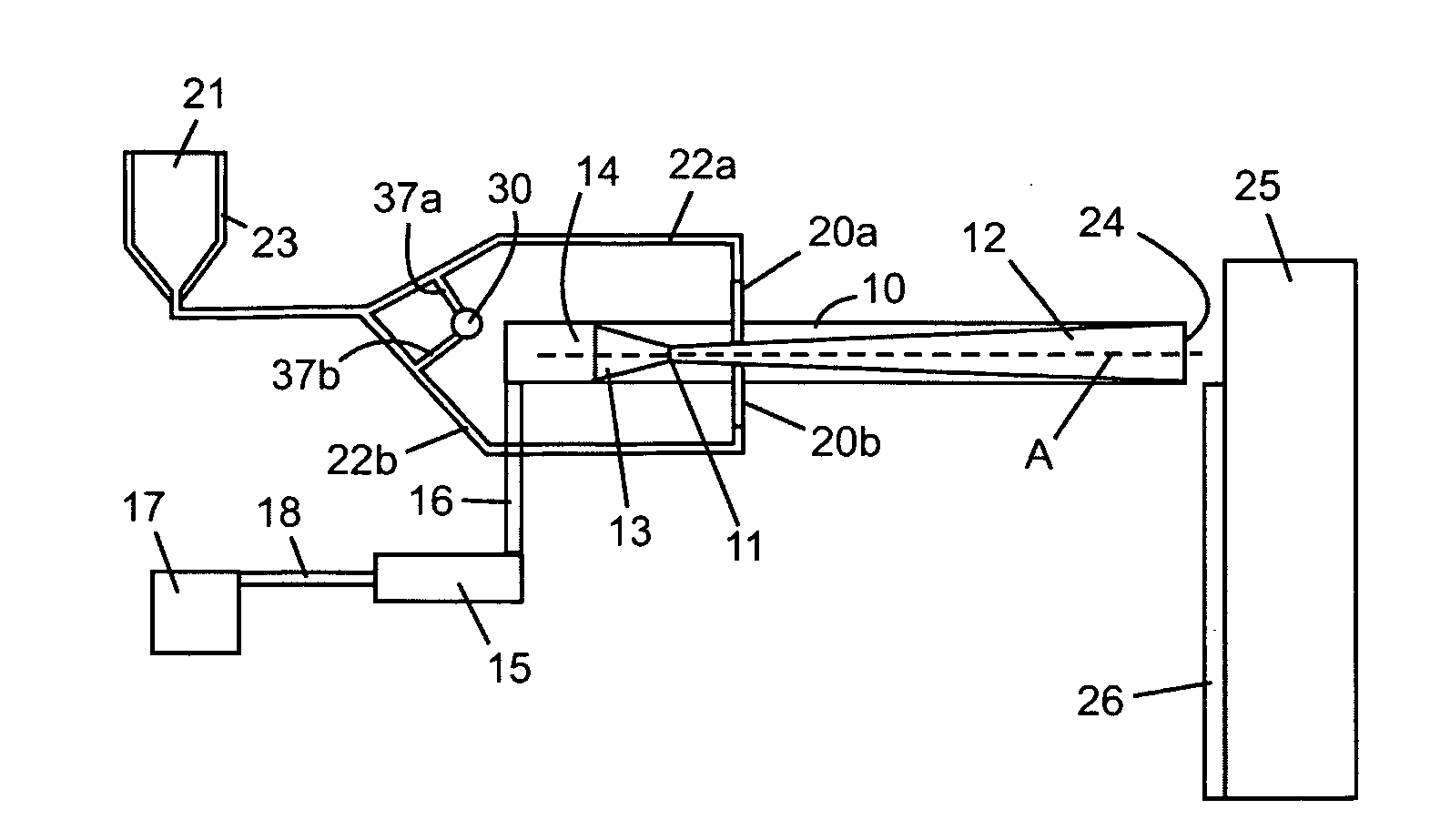
[0082]A typical de Laval type nozzle is used having a converging cone whose diameter decreases from 8.2 mm at the entrance to 2.5 mm at the throat. Downstream of the throat region is a diverging cone with a diameter of 4.88 mm at the outlet end. The total length of the diverging portion is typically 139 mm. Air is designed as the main working gas and powder carrier gas. The inlet pressure of compressed air can be adjusted to a preset value up to 830 kPa (120 psi). The main process gas temperature can be varied by an in-line heater in the range of 200° C. to 500° C. The powder is injected along the radial-inward direction of the nozzle, coming from a particle feeder, through a particle injector (c...

example 2

Nozzle Design

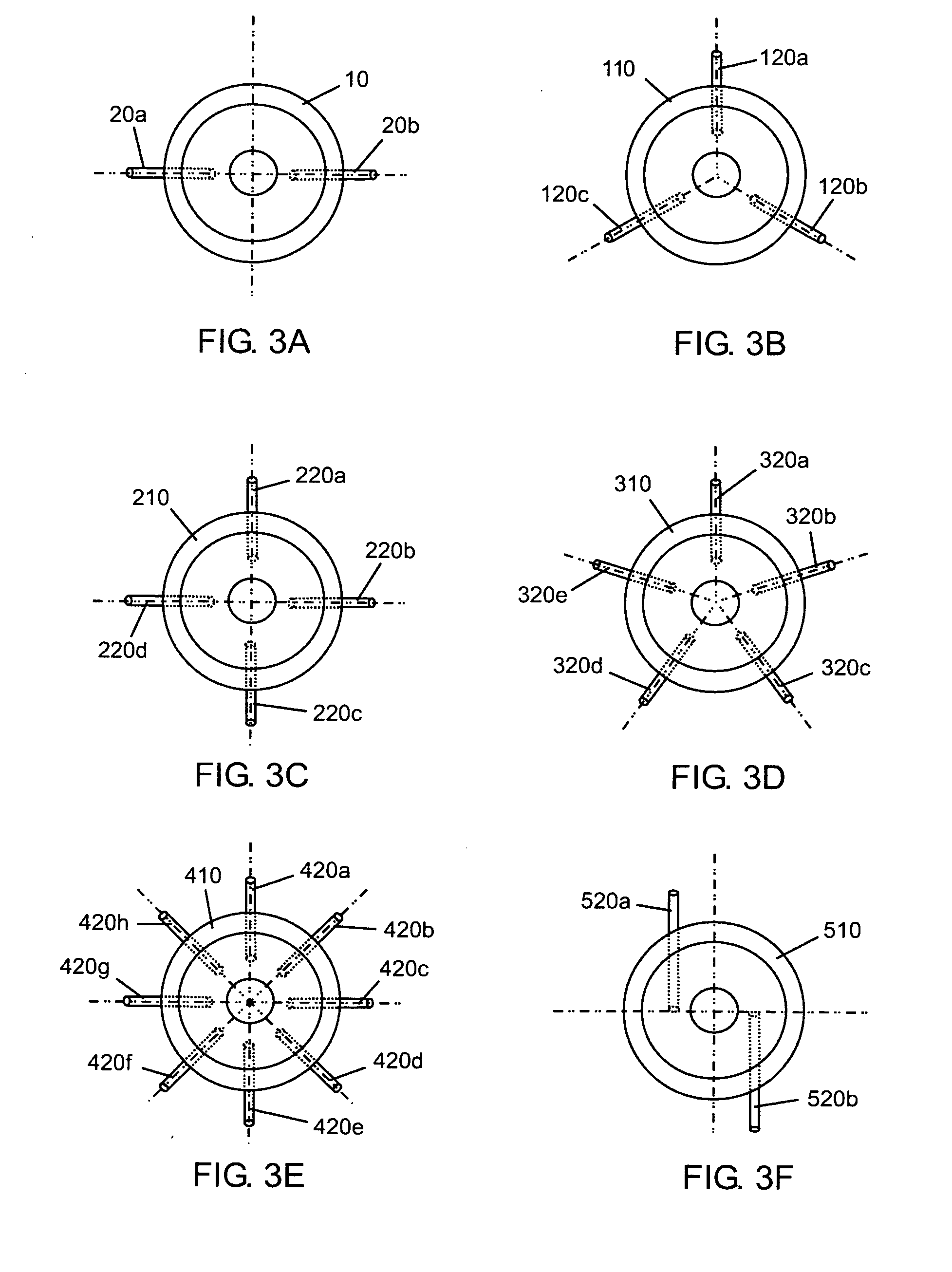
[0100]A nozzle for a cold spray system of the present invention has a total length of 220 mm, a throat diameter of 2.15 mm, a working gas inlet diameter of 8.2 mm, and a nozzle exit diameter of 6.5 mm. Two powder injectors with 45° injection angle are axis-symmetrically located around the nozzle downstream 13 mm from the nozzle throat. Pressurized powder injectors with a pressure up to 690 kPa (100 psi)) are used to allow higher inlet pressure (up to 3-4 MPa) and larger exit Mach number (up to 4).

example 3

Preliminary Validation Test

[0101]A preliminary test was performed using the nozzle design of Example 2. Particle exit velocities for the nozzle were measured at P0=2.5 MPa and T0=300 K. T0 is the inlet working gas temperature. Table 2 compares average measured particle velocity with average calculated particle velocity for this cold spray system. Also for comparison, Table 2 provides calculated results for different cold spray systems of the prior art.

[0102]The results in Table 2 show that the measured average particle velocity (400 m / s) from the system of the present invention is in good agreement with the predicted average particle velocity (430 m / s). It also demonstrated that the system of the present invention has much higher particle exit velocity as compared to the commercial downstream system (only about 285 m / s) and is comparable to the results of upstream system (455 m / s) even at the current simulation conditions. Thus, systems of the present invention combine the low cost ...


PUM

PropertyMeasurementUnit
cross-sectional areaaaaaaaaaaa
lengthaaaaaaaaaa

Abstract

A system for cold gas dynamic spraying of particulate material has a de Laval nozzle and two or more radial particle inlets located between the throat and the outlet of the nozzle, the two or more particle inlets arranged symmetrically around a linear flow path of the nozzle. Blocking of the inlets is reduced by controlling pressure of particle carrier gas to provide a stable particulate material injection pressure before and during introduction of working gas into the nozzle, and/or by clearing the particle inlets of residual particles after a spraying process. Such a system and associated method combines benefits of both downstream and upstream cold gas spray systems. Further, a nozzle for spraying particulate material having a cross-sectional shape that is narrower in a middle section compared to edge sections provides coatings with superior cross-sectional profiles.

Description

CROSS-REFERENCE TO RELATED APPLICATIONS[0001]This application claims the benefit of U.S. Provisional Patent Application Ser. No. 61 / 193,659 filed Dec. 12, 2008, the entire contents of which is herein incorporated by reference.FIELD OF THE INVENTION[0002]The present invention relates to cold gas dynamic spray apparatuses, systems and methods, in particular to such apparatuses, systems and methods for coating of particles on a substrate.BACKGROUND OF THE INVENTION[0003]Cold spray is a relatively new technology that has many advantages over conventional thermal spray processes. It is a solid-state coating and material deposition process in which small solid particles are accelerated to high velocities (e.g. 300 to 1200 m / s) by a supersonic or sub-supersonic jet flow through a de Laval nozzle and are subsequently deposited onto the substrate through an impact process to form a coating or deposition. When the high velocity particles impact on a substrate, severe plastic deformation occur...

Claims


Application Information

Patent Timeline
Patent Type & Authority Applications(United States)
IPC IPC(8): B05D1/12B05C5/00B05B7/04
CPCC23C24/04B05B7/1486C23C4/08C23C4/12
Inventor XUE, LIJUEWANG, SHAODONGJIANG, JIAREN
Owner NAT RES COUNCIL OF CANADA
Why Eureka
Try Eureka