Wireline communication system for deep wells

a communication system and wireline technology, applied in the direction of instruments, borehole/well accessories, surveys, etc., can solve the problems of virtually impossible to know the exact location of the well at a given depth, severe difficulties, and difficult to precisely control the path followed by the well, so as to improve the accuracy of the measurement of the decay field and improve the accuracy of the magnetic field measuremen

Active Publication Date: 2010-06-24
HALLIBURTON ENERGY SERVICES INC
View PDF1 Cites 61 Cited by
  • Summary
  • Abstract
  • Description
  • Claims
  • Application Information

AI Technical Summary

Benefits of technology

[0017]In another embodiment of the invention, magnetic field measurement accuracy may be improved in some circumstances by operating the system in a pulsed transient mode, wherein the earth formations surrounding the relief and the target wells are energized by a stepped, or pulsed, primary excitation current from a power source which preferably is at the surface, and measurements of magnetic fields produced by the resulting current flow in the target are made immediately following a stepwise turn-off of the excitation current, when that current is zero. Each pulse of electrical energy supplied to the wireline electrode causes a current to flow through the earth's formations to the target, and, as described in the foregoing U.S. Pat. No. 4,700,142, this current is collected on the electrically conductive target. The resulting target current flow creates a characteristic target magnetic field that is detected by the drill bit sensor instrument. In the pulsed, or transient, mode of operation of the present invention, the magnetic field measurement is made after the primary energizing current stops. The magnetic fields that are measured when the excitation current is zero are caused by a decaying target well current flow. Although this decay current produces only a very small field, since even the primary target current typically is only a few percent of the energizing current, the measurement of the decay field is more accurate, since interfering fields caused by the primary electrode current in the earth are not present.
[0018]To enhance this transient pulsed current magnetic field measurement, the drill string of the present invention incorporates at least two spaced, electrically isolated conductive drill string pipe sections, each separated from each other and other adjoining pipe sections by one or more electrically insulating subs. Deep well measurements are made by aligning corresponding spaced-apart wireline electrodes with the approximate centers of corresponding isolated drill pipe sections to effectively produce two drill pipe injection electrodes spaced along the drill string above the drill motor, by supplying a time-variable current to the electrodes to inject a current in the earth and producing a corresponding time-varying target current, and by detecting the resulting target magnetic field vectors at the location of a drill bit sub. Telemetry at the drill bit sub transmits the detected vector data uphole for use in calculating the distance and direction from the drill bit sub to the target.

Problems solved by technology

It is well known that in drilling boreholes in the earth, such as deep wells for oil and gas exploration, precise control of the path followed by the well is extremely difficult, so that it is virtually impossible to know the exact location of the well at a given depth.
This is not of particular concern in many drilling operations, but if drilling precision is necessary, as where a borehole is to be drilled precisely to a target location, such variations can cause severe difficulties.
In order to do this, the relief well must be drilled to intersect the original well at the desired level, and since such ruptures, or blowouts, often produce extremely hazardous conditions at the surface in the vicinity of the original well, the relief well usually must be started a considerable distance away from the original wellhead and drilled at an incline down to the desired point of intersection.
Because the same problems of control of the direction of drilling that were encountered in the original well are also encountered in drilling the relief well, the location of the relief well borehole also cannot be known with precision; accordingly, it is extremely difficult to determine the distance and direction from the end of the relief well to the desired point of intersection on the target well.
In addition, the relief well usually is very complex, compounding the problem of knowing exactly where it is located with respect to a target that may be 10 inches in diameter at a distance of thousands of feet below the earth's surface.
Some utilized surveying techniques to locate the relief well with respect to a target well, but such survey techniques are not capable of providing accurate data concerning the relationship of the relief well to the original well until the relief well has approached very near the original well.
Magnetic gradient ranging equipment can be used with considerable accuracy at close range; however, it has been found that outside a radius of a few tens of feet, such systems are usually inadequate.
Some of these systems are directed to the measurement of the apparent resistivity of the earth across a pair of electrodes but, since no directionality is given by this method, it is ineffective for directing a relief well toward an existing well.
However, such systems do not suggest the possibility of locating relatively small targets such as well bores.
However, such systems will not operate when there is no sound emanating from the target well, and, in addition, do not provide the required degree of directional and distance accuracy.
In these latter systems, however, the target well must be accessible so that the signal source can be placed in one well and the receiver in the other, and they are not effective where the target well is not open.
This need for making so many measurements makes the drilling of a relief well very expensive, especially in off-shore drilling, wherein, using the prior methods, the drill string for the relief well must be pulled for each measurement.
Since a drilling rig operation can cost upwards of $500,000.00 per day in offshore drilling operations, the time-consuming process of halting the drilling, withdrawing the drill string, and positioning the measuring equipment is an extremely expensive procedure Accordingly, a method and apparatus for making such measurements without the effort and expense of pulling the drill string is needed.
As a result of this, the MWD instrument is typically located 10-20 meters above the face of the drill bit, so that when magnetic field measurements are made with the drill string in the relief well, they are actually made a considerable distance from the drill bit, introducing a significant error in determination of the relative distance and direction of the target with respect to the drill bit.
This greatly increases the difficulty of accurately controlling the intersection of the borehole being drilled with the target.

Method used


Image

  • Wireline communication system for deep wells
  • Wireline communication system for deep wells
  • Wireline communication system for deep wells

Examples


Embodiment Construction

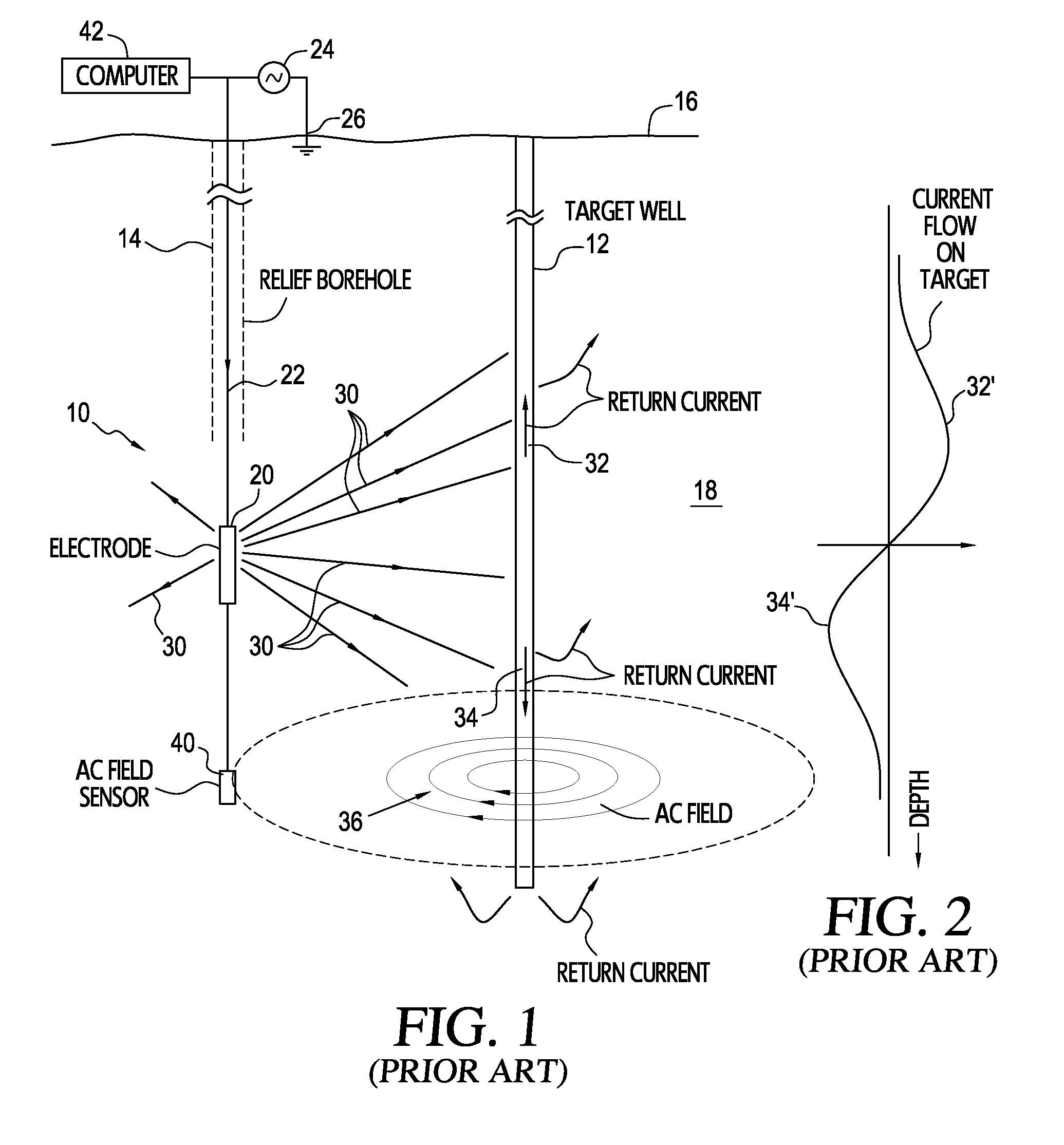
[0031]Turning now to a more detailed consideration of the present invention, FIG. 1 illustrates, in diagrammatic form, a standard well locating system 10 such as that described in U.S. Pat. No. 4,700,142, the disclosure of which is hereby incorporated herein by reference. In such a system, a target well 12 is to be intersected by drilling a relief borehole, or well, 14 along a path that will intersect the target at a desired depth below the earth's surface 16. The target well is cased, or has a drill string or other electrically conductive material in it, so that electrical current flowing in the earth's formations 18 surrounding the well 12 will tend to be concentrated on that conductive material. An alternating electrical current is injected into the earth by an electrode 20 carried by a logging cable, or wireline 22, which is lowered into the relief borehole 14 after the drill string that is used to drill the relief borehole has been pulled out. The electrode is connected through...


PUM


Abstract

A wireline apparatus for deep well measurements in a borehole being drilled includes a drill string having multiple drill pipe sections connected end-to-end, with at least one of the drill pipe sections being electrically conductive and isolated to provide an electrode section. A nonmagnetic drill pipe section is connected in the drill string below said electrode section, and a hydraulic motor having a rotatable drill bit carrying a drill bit instrument sub having a magnetic field sensing instrument package is connected to a lowermost end of the drill string. A wireline locatable within said drill string incorporates an electrode locatable within the drill pipe electrode section, and carries at its distal end a wireline instrument package that is locatable within the nonmagnetic drill pipe section to receive data representing magnetic field data from the magnetic field sensing instrument package. A time-variable AC source is connected to the wireline to energize the drill pipe electrode section by way of the wireline electrode to produce a corresponding target current magnetic field to be detected at the drill bit instrument.

Description

FIELD OF THE INVENTION[0001]The present invention relates, in general, to methods and apparatus for locating the distance and direction to a conductive target, such as a cased well or borehole, from a remote location such as a rescue borehole or well to obtain data for use in guiding the direction of drilling the rescue well to intersect the target, and, more particularly, to methods and apparatus for injecting time-varying electrical currents into the earth from one or more electrodes in the rescue borehole, for detecting at the drill bit of the rescue well electromagnetic field vectors resulting from such injected currents flowing in the target, and for transmitting data representing the detected fields to the earth's surface.BACKGROUND OF THE INVENTION[0002]It is well known that in drilling boreholes in the earth, such as deep wells for oil and gas exploration, precise control of the path followed by the well is extremely difficult, so that it is virtually impossible to know the ...

Claims


Application Information

Patent Timeline
Patent Type & Authority Applications(United States)
IPC IPC(8): E21B47/02G01V3/08G01V3/26E21B7/04E21B47/12E21B47/00
CPCE21B47/022G01V3/24E21B47/02216E21B47/0228
Inventor KUCKES, ARTHUR F.
Owner HALLIBURTON ENERGY SERVICES INC
Why Eureka
Try Eureka